 |
am3zzw00034772
FUEL INJECTOR INSPECTION [SKYACTIV-G (WITH CYLINDER DEACTIVATION (E))]
id0114u3800700
Fuel Injector Operation Inspection
1. Connect the M-MDS to the DLC-2.
2. Start the engine and warm it up.
3. Perform the KOER self-test and verify that none of the following DTCs is detected. (See DTC INSPECTION.)
4. If any of the following DTCs can be verified, perform the applicable DTC inspection. (See DTC TABLE [PCM (SKYACTIV-G (E))].)
5. Monitor the engine speed (ENG_RPM) signal using the PID/data monitor function. (See PID/DATA MONITOR INSPECTION.)
6. Using the simulation function [INJ], verify that the PID [ENG_RPM] decreases when operation of each injector is stopped. (See SIMULATION INSPECTION.)
Fuel Cut Control Inspection
1. Connect the M-MDS to the DLC-2.
2. Warm up the engine and idle it.
3. Load the vehicle on a chassis dynamometer or drive the vehicle on a road.
4. Verify the PIDs [ENG_RPM] and [FUEL_PULSE_WD] using the PID/data monitor function. (See PID/DATA MONITOR INSPECTION.)
5. Drive the vehicle while verifying the PID [ENG_RPM] and maintain the engine speed at 4,000 rpm or more.
6. When the accelerator pedal is released without depressing the brake pedal, verify that the PID [FUEL_PULSE_WD] indicates 0 ms until the PID [ENG_RPM] reaches approx. 1,200 rpm and the PID [FUEL_PULSE_WD] indicates 2 to 5 ms when the PID [ENG_RPM] is approx. 1,200 rpm or less.
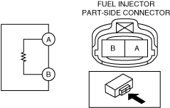
Resistance Inspection
1. Disconnect the negative battery terminal. (See NEGATIVE BATTERY TERMINAL DISCONNECTION/CONNECTION [(E)].)
2. Disconnect the fuel injector connector. (See FUEL INJECTOR REMOVAL/INSTALLATION [SKYACTIV-G (WITH CYLINDER DEACTIVATION (E))].)
3. Inspect the resistance between fuel injector terminals A and B.
am3zzw00034772
|