 |
am6zzw00012042
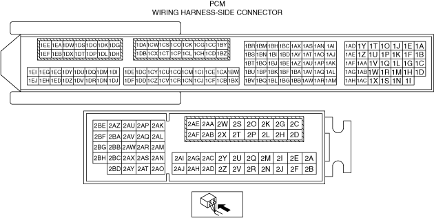
PCM INSPECTION [SKYACTIV-D 1.8]
id0140s1113900
Terminal Voltage Table (Reference)
am6zzw00012042
|
|
Terminal |
Signal |
Connected to |
Test condition |
Voltage (V) |
inspection item |
|
|---|---|---|---|---|---|---|
|
1A
|
CMP (G+)
|
CMP sensor
|
(See CMP (G+) signal.)
|
• CMP sensor
• Related wiring harness
|
||
|
1B
|
CMP (G–)
|
CMP sensor
|
Switch the ignition ON (engine off)
|
Approx. 0.09
|
• CMP sensor
• Related wiring harness
|
|
|
1C
|
—
|
—
|
—
|
—
|
—
|
|
|
1D
|
Generator output voltage
|
Generator
|
(See Generator output voltage.)
|
• Generator
• Related wiring harness
|
||
|
1E
|
CKP (NE+)
|
CKP sensor
|
(See CKP (NE+) signal.)
|
• CKP sensor
• Related wiring harness
|
||
|
1F
|
CKP (NE–)
|
CKP sensor
|
Switch the ignition ON (engine off)
|
Approx. 0.09
|
• CKP sensor
• Related wiring harness
|
|
|
1G
|
GND
|
Exhaust gas pressure sensor No.2
|
Under any condition
|
Approx. 0
|
• GND point
• Related wiring harness
|
|
|
1H
|
A/F (+)
|
A/F sensor
|
Idle (after warm up)
|
Approx. 3.23
|
• A/F sensor
• Related wiring harness
|
|
|
1I
|
A/F (−)
|
A/F sensor
|
Idle (after warm up)
|
Approx. 2.74
|
• A/F sensor
• Related wiring harness
|
|
|
1J
|
Constant voltage (Vref)
|
CKP sensor
|
Switch the ignition ON (engine off)
|
Approx. 5.1
|
• Related wiring harness
|
|
|
1K
|
Constant voltage (Vref)
|
CMP sensor
|
Switch the ignition ON (engine off)
|
Approx. 5.1
|
• Related wiring harness
|
|
|
1L
|
GND
|
Engine oil level sensor
|
Under any condition
|
Approx. 0
|
• GND point
• Related wiring harness
|
|
|
1M
|
Constant voltage (Vref)
|
Fuel pressure sensor (in fuel injector No.1)
|
Switch ignition ON (engine off)
|
Approx. 5.1
|
• Related wiring harness
|
|
|
1N
|
Constant voltage (Vref)
|
Fuel pressure sensor (in fuel injector No.4)
|
Switch ignition ON (engine off)
|
Approx. 5.1
|
• Related wiring harness
|
|
|
1O
|
—
|
—
|
—
|
—
|
—
|
|
|
1P
|
LIN
|
Fuel temperature sensor (in fuel injector No.3)
|
Because this terminal is for communication, integrity determination using terminal voltage inspection is not possible.
|
• Related wiring harness
|
||
|
1Q
|
GND
|
HP-EGR control valve position sensor
|
Under any condition
|
Approx. 0
|
• GND point
• Related wiring harness
|
|
|
1R
|
GND
|
Fuel pressure sensor (in fuel injector No.1)
|
Under any condition
|
Approx. 0
|
• GND point
• Related wiring harness
|
|
|
1S
|
GND
|
Fuel pressure sensor (in fuel injector No.4)
|
Under any condition
|
Approx. 0
|
• GND point
• Related wiring harness
|
|
|
1T
|
LIN
|
Fuel temperature sensor (in fuel injector No.1)
|
Because this terminal is for communication, integrity determination using terminal voltage inspection is not possible.
|
• Related wiring harness
|
||
|
1U
|
LIN
|
Fuel temperature sensor (in fuel injector No.4)
|
Because this terminal is for communication, integrity determination using terminal voltage inspection is not possible.
|
• Related wiring harness
|
||
|
1V
|
LIN
|
Fuel temperature sensor (in fuel injector No.2)
|
Because this terminal is for communication, integrity determination using terminal voltage inspection is not possible.
|
• Related wiring harness
|
||
|
1W*2
|
Constant voltage (Vref)
|
Neutral sensor No.2
|
Switch ignition ON (engine off)
|
Approx. 5.1
|
• Neutral sensor No.2
• Related wiring harness
|
|
|
1X
|
—
|
—
|
—
|
—
|
—
|
|
|
1Y*1
|
CAN_2L
|
CAN system related modules
|
Because this terminal is for CAN, good/no good judgment by terminal voltage is not possible.
|
• Related wiring harness
|
||
|
1Z
|
Exhaust gas pressure
|
Exhaust gas pressure sensor No.2
|
Switch the ignition ON (engine off)
|
Approx. 0.50
|
• Exhaust gas pressure sensor No.2
• Related wiring harness
|
|
|
Idle (after warm up)
|
0.575—0.614
|
|||||
|
1AA
|
GND
|
Sensor shield
|
Under any condition
|
Approx. 0
|
• GND point
• Related wiring harness
|
|
|
1AB
|
IAT (No.2)
|
IAT sensor No.2
|
IAT (No.2) 20 °C {68 °F}
|
Approx. 3.57
|
• IAT sensor No.2
• Related wiring harness
|
|
|
IAT (No.2) 40 °C {104 °F}
|
Approx. 2.70
|
|||||
|
IAT (No.2) 60 °C {140 °F}
|
Approx. 1.87
|
|||||
|
1AC
|
GND
|
Sensor shield
|
Under any condition
|
Approx. 0
|
• GND point
• Related wiring harness
|
|
|
1AD
|
CAN_2H
|
CAN system related modules
|
Because this terminal is for CAN, good/no good judgment by terminal voltage is not possible.
|
• Related wiring harness
|
||
|
1AE
|
GND
|
Sensor shield
|
Under any condition
|
Approx. 0
|
• GND point
• Related wiring harness
|
|
|
1AF
|
GND
|
Sensor shield
|
Under any condition
|
Approx. 0
|
• GND point
• Related wiring harness
|
|
|
1AG
|
Fuel pressure No.1
|
Fuel pressure sensor (in fuel injector No.1)
|
Switch the ignition ON (engine off)/fuel pressure: 0 MPa {0 kgf/cm2, 0 psi}
|
Approx. 0.950
|
• Fuel pressure sensor (in fuel injector No.1)
• Related wiring harness
|
|
|
Idle (after warm up)/fuel pressure: 200—275 MPa {2040—2804 kgf/cm2, 29008—39885 psi}
|
1.447—1.462
|
|||||
|
1AH
|
GND
|
Sensor shield
|
Under any condition
|
Approx. 0
|
• GND point
• Related wiring harness
|
|
|
1AI
|
CAN_2H
|
CAN system related modules
|
Because this terminal is for CAN, good/no good judgment by terminal voltage is not possible.
|
• Related wiring harness
|
||
|
1AJ
|
Coolant control valve (3WAY−)
|
Coolant control valve
|
Switch ignition ON (engine off)
|
Approx. 12.36
|
• Coolant control valve
• Related wiring harness
|
|
|
Idle (when cold)
|
Approx. 0.087
|
|||||
|
Idle (after warm up)
|
Approx. 14.33
|
|||||
|
1AK
|
Constant voltage (Vref)
|
Exhaust gas pressure sensor No.2
|
Switch the ignition ON (engine off)
|
Approx. 5.1
|
• Related wiring harness
|
|
|
1AL*2
|
NS_SUB
|
Neutral sensor No.2
|
Shift lever is at neutral position
|
Below 1.0
|
• Neutral sensor No.2
• Related wiring harness
|
|
|
Shift lever is not at neutral position
|
Approx. 4.5
|
|||||
|
1AM
|
Fuel pressure No.3
|
Fuel pressure sensor (in fuel injector No.3)
|
Switch the ignition ON (engine off)/fuel pressure: 0 MPa {0 kgf/cm2, 0 psi}
|
Approx. 0.950
|
• Fuel pressure sensor (in fuel injector No.3)
• Related wiring harness
|
|
|
Idle (after warm up)/fuel pressure: 200—275 MPa {2040—2804 kgf/cm2, 29008—39885 psi}
|
1.447—1.462
|
|||||
|
1AN
|
CAN_2H
|
CAN system related modules
|
Because this terminal is for CAN, good/no good judgment by terminal voltage is not possible.
|
• Related wiring harness
|
||
|
1AO
|
Coolant control valve (3WAY+)
|
Coolant control valve
|
Switch ignition ON (engine off)
|
Approx. 12.68
|
• Coolant control valve
• Related wiring harness
|
|
|
1AP
|
Constant voltage (Vref)
|
HP-EGR control valve position sensor
|
Switch ignition ON (engine off)
|
Approx. 5.1
|
• Related wiring harness
|
|
|
1AQ
|
HP-EGR control valve position
|
HP-EGR control valve position sensor
|
Switch ignition ON (engine off)
|
Approx. 1.242
|
• HP-EGR control valve
• Related wiring harness
|
|
|
Idle (after warm up)
|
Approx. 2.11
|
|||||
|
1AR*2
|
GND
|
Revolution sensor, neutral sensor No.1
|
Under any condition
|
Approx. 0
|
• GND point
• Related wiring harness
|
|
|
1AS
|
Intake shutter valve (ISV+)
|
Intake shutter valve
|
Switch the ignition ON (engine off)
|
Approx. 0.051
|
• Intake shutter valve
• Related wiring harness
|
|
|
1AT
|
GND
|
LP-EGR control valve position sensor
|
Under any condition
|
Approx. 0
|
• GND point
• Related wiring harness
|
|
|
1AU
|
Constant voltage (Vref)
|
LP-EGR control valve position sensor
|
Switch ignition ON (engine off)
|
Approx. 5.1
|
• Related wiring harness
|
|
|
1AV
|
LP-EGR control valve position
|
LP-EGR control valve position sensor
|
Switch ignition ON (engine off)
|
Approx. 1.24
|
• LP-EGR control valve position sensor
• Related wiring harness
|
|
|
Idle (after warm up)
|
Approx. 1.29
|
|||||
|
1AW
|
GND
|
Exhaust gas temperature sensor No.1
|
Under any condition
|
Approx. 0
|
• GND point
• Related wiring harness
|
|
|
1AX
|
Intake shutter valve (ISV-)
|
Intake shutter valve
|
Switch the ignition ON (engine off)
|
Approx. 0.027
|
• Intake shutter valve
• Related wiring harness
|
|
|
Idle (after warm up)
|
0.2—0.8
|
|||||
|
1AY
|
GND
|
Intake shutter valve position sensor
|
Under any condition
|
Approx. 0
|
• GND point
• Related wiring harness
|
|
|
1AZ
|
Constant voltage (Vref)
|
Intake shutter valve position sensor
|
Switch the ignition ON (engine off)
|
Approx. 5.1
|
• Related wiring harness
|
|
|
1BA
|
Intake shutter valve position
|
Intake shutter valve position sensor
|
Switch the ignition ON (engine off)
|
Approx. 4.27
|
• Intake shutter valve position sensor
• Related wiring harness
|
|
|
Idle (after warm up)
|
Approx. 0.68
|
|||||
|
1BB
|
GND
|
IAT sensor No.3
|
Under any condition
|
Approx. 0
|
• GND point
• Related wiring harness
|
|
|
1BC
|
LP-EGR control valve (LPEGR−)
|
LP-EGR control valve
|
Switch ignition ON (engine off)
|
Approx. 0.027
|
• LP-EGR control valve
• Related wiring harness
|
|
|
1BD
|
—
|
—
|
—
|
—
|
—
|
|
|
1BE
|
—
|
—
|
—
|
—
|
—
|
|
|
1BF*2
|
Revolution
|
Revolution sensor
|
(See Revolution sensor signal.)
|
• Revolution sensor
• Related wiring harness
|
||
|
1BG
|
Fuel pressure No.4
|
Fuel pressure sensor (in fuel injector No.4)
|
Switch the ignition ON (engine off)/fuel pressure: 0 MPa {0 kgf/cm2, 0 psi}
|
Approx. 0.950
|
• Fuel pressure sensor (in fuel injector No.4)
• Related wiring harness
|
|
|
Idle (after warm up)/fuel pressure: 200—275 MPa {2040—2804 kgf/cm2, 29008—39885 psi}
|
1.447—1.462
|
|||||
|
1BH
|
LP-EGR control valve (LPEGR+)
|
LP-EGR control valve
|
Switch ignition ON (engine off)
|
Approx. 0.027
|
• LP-EGR control valve
• Related wiring harness
|
|
|
Idle (after warm up)
|
Approx. 14.29
|
|||||
|
1BI
|
—
|
—
|
—
|
—
|
—
|
|
|
1BJ
|
—
|
—
|
—
|
—
|
—
|
|
|
1BK
|
Boost air temperature
|
Boost air temperature sensor
|
Boost air temperature: 25 °C {77 °F}
|
Approx. 3.07
|
• Boost air temperature sensor
• Related wiring harness
|
|
|
1BL
|
Fuel pressure No.2
|
Fuel pressure sensor (in fuel injector No.2)
|
Switch the ignition ON (engine off)/fuel pressure: 0 MPa {0 kgf/cm2, 0 psi}
|
Approx. 0.950
|
• Fuel pressure sensor (in fuel injector No.2)
• Related wiring harness
|
|
|
Idle (after warm up)/fuel pressure: 200—275 MPa {2040—2804 kgf/cm2, 29008—39885 psi}
|
3.150—3.975
|
|||||
|
1BM
|
HP-EGR control valve (EGRH−)
|
HP-EGR control valve
|
Switch ignition ON (engine off)
|
Approx. 0.027
|
• HP-EGR control valve
• Related wiring harness
|
|
|
Idle (when cold)
|
Approx. 0.18
|
|||||
|
Idle (after warm up)
|
0.124—0.263
|
|||||
|
1BN
|
GND
|
Coolant control valve position sensor
|
Under any condition
|
Approx. 0
|
• GND point
• Related wiring harness
|
|
|
1BO
|
Constant voltage (Vref)
|
Coolant control valve position sensor
|
Switch ignition ON (engine off)
|
Approx. 5.1
|
• Related wiring harness
|
|
|
1BP
|
Coolant control valve position
|
Coolant control valve position sensor
|
Switch ignition ON (engine off)
|
Approx. 4.38
|
• Coolant control valve
• Related wiring harness
|
|
|
Idle (when cold)
|
Approx. 1.4
|
|||||
|
Idle (after warm up)
|
Approx. 2.8
|
|||||
|
1BQ
|
GND
|
Fuel pressure sensor (in fuel injector No.3)
|
Under any condition
|
Approx. 0
|
• GND point
• Related wiring harness
|
|
|
1BR
|
HP-EGR control valve (EGRH+)
|
HP-EGR control valve
|
(See HP-EGR control valve (EGRH+).)
|
• HP-EGR control valve
• Related wiring harness
|
||
|
1BS
|
GND
|
Exhaust gas temperature sensor No.3
|
Under any condition
|
Approx. 0
|
• GND point
• Related wiring harness
|
|
|
1BT*2
|
Constant voltage (Vref)
|
Revolution sensor, neutral sensor No.1
|
Switch the ignition ON (engine off)
|
Approx. 5.1
|
• Revolution sensor
• Neutral sensor No.1
• Related wiring harness
|
|
|
1BU*2
|
NS_MAIN
|
Neutral sensor No.1
|
Shift lever is at neutral position
|
Below 0
|
• Neutral sensor No.1
• Related wiring harness
|
|
|
Shift lever is not at neutral position
|
4.0—5.0
|
|||||
|
1BV
|
Constant voltage (Vref)
|
Fuel pressure sensor (in fuel injector No.3)
|
Switch the ignition ON (engine off)
|
Approx. 5.1
|
• Related wiring harness
|
|
|
1BW
|
Exhaust gas temperature (No.3)
|
Exhaust gas temperature sensor No.3
|
Exhaust gas temperature (No.3): 25 °C {77 °F}
|
Approx. 2.89
|
• Exhaust gas temperature sensor No.3
• Related wiring harness
|
|
|
1BX
|
Constant voltage (Vref)
|
Fuel pressure sensor (in fuel injector No.2)
|
Switch the ignition ON (engine off)
|
Approx. 5.1
|
• Related wiring harness
|
|
|
1BY
|
Suction control valve
|
Suction control valve
|
Switch ignition ON (engine off)
|
Approx. 0.01
|
• Suction control valve
• Related wiring harness
|
|
|
Idle (after warm up)
|
Approx. 0.24
|
|||||
|
1BZ
|
—
|
—
|
—
|
—
|
—
|
|
|
1CA
|
Exhaust gas temperature
|
Exhaust gas temperature sensor No.2
|
Switch the ignition ON (engine off)
|
Approx. 5.03
|
• Exhaust gas temperature sensor No.2
• Related wiring harness
|
|
|
1CB
|
GND
|
Exhaust gas temperature sensor No.2
|
Under any condition
|
Approx. 0
|
• GND point
• Related wiring harness
|
|
|
1CC
|
Suction control valve
|
Suction control valve
|
Switch the ignition ON (engine off)
|
0.038—0.041
|
• Suction control valve
• Related wiring harness
|
|
|
(See Suction control valve signal.)
|
||||||
|
1CD
|
—
|
—
|
—
|
—
|
—
|
|
|
1CE
|
Exhaust gas pressure
|
Exhaust gas pressure sensor No.1
|
Switch the ignition ON (engine off)
|
Approx. 0.957
|
• Exhaust gas pressure sensor No.1
• Related wiring harness
|
|
|
Idle (after warm up)
|
0.975—1.230
|
|||||
|
1CF
|
GND
|
Exhaust gas pressure sensor No.1
|
Under any condition
|
Approx. 0
|
• GND point
• Related wiring harness
|
|
|
1CG
|
A/F sensor heater control
|
A/F sensor heater
|
• A/F sensor heater
• Related wiring harness
|
|||
|
1CH
|
Engine oil control
|
Engine oil solenoid valve
|
(See Engine oil control signal.)
|
• Engine oil solenoid valve
• Related wiring harness
|
||
|
1CI
|
Exhaust gas temperature
|
Exhaust gas temperature sensor No.1
|
Switch the ignition ON (engine off)
|
Approx. 4.94
|
• Exhaust gas temperature sensor No.1
• Related wiring harness
|
|
|
1CJ
|
Constant voltage (Vref)
|
Exhaust gas pressure sensor No.1
|
Switch the ignition ON (engine off)
|
Approx. 5.1
|
• Related wiring harness
|
|
|
1CK
|
—
|
—
|
—
|
—
|
—
|
|
|
1CL
|
—
|
—
|
—
|
—
|
—
|
|
|
1CM
|
IAT (No.3)
|
IAT sensor No.3
|
IAT (No.3) 20 °C {68 °F}
|
Approx. 3.57
|
• IAT sensor No.3
• Related wiring harness
|
|
|
IAT (No.3) 40 °C {104 °F}
|
Approx. 2.70
|
|||||
|
IAT (No.3) 60 °C {140 °F}
|
Approx. 1.87
|
|||||
|
1CN
|
Constant voltage (Vref)
|
MAP sensor, boost air temperature sensor
|
Switch the ignition ON (engine off)
|
Approx. 5.1
|
• Related wiring harness
|
|
|
1CO
|
Turbocharger solenoid valve
|
Turbocharger solenoid valve
|
Switch ignition ON (engine off)
|
Approx. 12.19
|
• Turbocharger solenoid valve
• Related wiring harness
|
|
|
(See Turbocharger solenoid valve.)
|
||||||
|
1CP
|
Electric water pump
|
Electric water pump
|
Switch ignition ON (engine off)
|
E_WATER_PUMP 0%:
|
Approx. 0.034
|
• Electric water pump
• Related wiring harness
|
|
E_WATER_PUMP 95%
|
Approx. 10.38
|
• Electric water pump
• Related wiring harness
|
||||
|
1CQ
|
MAP
|
MAP sensor
|
Switch the ignition ON (engine off)
|
Approx. 1.646
|
• MAP sensor
• Related wiring harness
|
|
|
Idle (after warm up)
|
1.380—1.580
|
|||||
|
1CR
|
GND
|
MAP sensor, boost air temperature sensor
|
Under any condition
|
Approx. 0
|
• GND point
• Related wiring harness
|
|
|
1CS
|
Fuel injection control (−)
|
Fuel injector No.3
|
• Fuel injector No.3
• Related wiring harness
|
|||
|
1CT
|
Fuel injection control (−)
|
Fuel injector No.2
|
• Fuel injector No.2
• Related wiring harness
|
|||
|
1CU
|
—
|
—
|
—
|
—
|
—
|
|
|
1CV*2
|
GND
|
Revolution sensor, neutral sensor No.2
|
Under any condition
|
Approx. 0
|
• GND point
• Related wiring harness
|
|
|
1CW
|
Fuel injection control (+)
|
Fuel injector No.2
|
• Fuel injector No.2
• Related wiring harness
|
|||
|
1CX
|
—
|
—
|
—
|
—
|
—
|
|
|
1CY
|
—
|
—
|
—
|
—
|
—
|
|
|
1CZ
|
GND
|
IAT sensor No.1
|
Under any condition
|
Approx. 0
|
• GND point
• Related wiring harness
|
|
|
1DA
|
Fuel injection control (+)
|
Fuel injector No.3
|
• Fuel injector No.3
• Related wiring harness
|
|||
|
1DB
|
—
|
—
|
—
|
—
|
—
|
|
|
1DC
|
ECT
|
ECT sensor
|
Engine coolant temperature: 25 °C {77 °F}
|
Approx. 2.11
|
• ECT sensor
• Related wiring harness
|
|
|
1DD
|
GND
|
ECT sensor
|
Under any condition
|
Approx. 0
|
• GND point
• Related wiring harness
|
|
|
1DE
|
Constant voltage (Vref)
|
Actuator position sensor (turbocharger with variable turbine geometry)
|
Switch ignition ON (engine off)
|
Approx. 5.1
|
• Related wiring harness
|
|
|
1DF
|
GND
|
Sensor shield
|
Under any condition
|
Approx. 0
|
• GND point
• Related wiring harness
|
|
|
1DG
|
PRD−
|
Fuel pressure relief valve
|
Switch ignition ON (engine off)
|
Approx. 4.73
|
• Fuel pressure relief valve
• Related wiring harness
|
|
|
Idle (after warm up)
|
Approx. 4.85
|
|||||
|
1DH
|
Battery voltage
|
Main relay
|
Switch the ignition ON (engine off)
|
Approx. 12.12
|
• Main relay
• Related wiring harness
|
|
|
1DI
|
Engine oil temperature
|
Engine oil temperature sensor
|
Engine oil temperature: 25 °C {77 °F}
|
Approx. 3.20
|
• Engine oil temperature sensor
• Related wiring harness
|
|
|
1DJ
|
GND
|
Engine oil temperature sensor, engine oil pressure sensor
|
Under any condition
|
Approx. 0
|
• GND point
• Related wiring harness
|
|
|
1DK
|
PRD+
|
Fuel pressure relief valve
|
Switch the ignition ON (engine off)
|
Approx. 4.73
|
• Fuel pressure relief valve
• Related wiring harness
|
|
|
Idle (after warm up)
|
Approx. 4.58
|
|||||
|
1DL
|
Battery voltage
|
Main relay
|
Switch the ignition ON (engine off)
|
Approx. 12.11
|
• Main relay
• Related wiring harness
|
|
|
1DM
|
Engine oil pressure
|
Engine oil pressure sensor
|
Switch the ignition ON (engine off)
|
Approx. 0.538
|
• Engine oil pressure sensor
• Related wiring harness
|
|
|
Idle (after warm up)
|
1.075—1.475
|
|||||
|
1DN
|
Constant voltage (Vref)
|
Engine oil temperature sensor, engine oil pressure sensor
|
Switch the ignition ON (engine off)
|
Approx. 5.1
|
• Related wiring harness
|
|
|
1DO
|
—
|
—
|
—
|
—
|
—
|
|
|
1DP
|
—
|
—
|
—
|
—
|
—
|
|
|
1DQ
|
EGR temperature
|
EGR temperature sensor
|
EGR temperature: 25 °C {77 °F}
|
Approx. 5.03
|
• EGR temperature sensor
• Related wiring harness
|
|
|
1DR
|
GND
|
Actuator position sensor (turbocharger with variable turbine geometry)
|
Under any condition
|
Approx. 0
|
• GND point
• Related wiring harness
|
|
|
1DS
|
—
|
—
|
—
|
—
|
—
|
|
|
1DT
|
GND
|
Sensor shield
|
Under any condition
|
Approx. 0
|
• GND point
• Related wiring harness
|
|
|
1DU
|
Exhaust gas temperature (No.4)
|
Exhaust gas temperature sensor No.4
|
Exhaust gas temperature (No.4): 25 °C{77 °F}
|
Approx. 4.99
|
• Exhaust gas temperature sensor No.4
• Related wiring harness
|
|
|
1DV
|
GND
|
Exhaust gas temperature sensor No.4
|
Under any condition
|
Approx. 0
|
• GND point
• Related wiring harness
|
|
|
1DW
|
Fuel injection control (+)
|
Fuel injector No.4
|
• Fuel injector No.4
• Related wiring harness
|
|||
|
1DX
|
—
|
—
|
—
|
—
|
—
|
|
|
1DY
|
Actuator position
|
Actuator position sensor (turbocharger with variable turbine geometry)
|
Switch the ignition ON (engine off)
|
Approx. 0.662
|
• Actuator position sensor (turbocharger with variable turbine geometry)
• Related wiring harness
|
|
|
Idle (after warm up)
|
Approx. 4.07
|
|||||
|
1DZ
|
GND
|
EGR temperature sensor
|
Under any condition
|
Approx. 0
|
• GND point
• Related wiring harness
|
|
|
1EA
|
Fuel injection control (+)
|
Fuel injector No.1
|
• Fuel injector No.1
• Related wiring harness
|
|||
|
1EB
|
GND
|
Sensor shield
|
Under any condition
|
Approx. 0
|
• GND point
• Related wiring harness
|
|
|
1EC
|
—
|
—
|
—
|
—
|
—
|
|
|
1ED
|
—
|
—
|
—
|
—
|
—
|
|
|
1EE
|
Fuel injection control (−)
|
Fuel injector No.1
|
• Fuel injector No.1
• Related wiring harness
|
|||
|
1EF
|
Fuel injection control (−)
|
Fuel injector No.4
|
• Fuel injector No.4
• Related wiring harness
|
|||
|
1EG*2
|
Neutral position
|
Neutral switch No.1
|
Shift lever is at neutral position
|
Below 1.0
|
• Neutral switch No.1
• Related wiring harness
|
|
|
Shift lever is not at neutral position
|
B+
|
|||||
|
1EH*2
|
Back-up light
|
Back-up light switch
|
Shift lever is at R position
|
Below 1.0
|
• Back-up light switch
• Related wiring harness
|
|
|
Shift lever is not at R position
|
B+
|
|||||
|
1EI
|
Generator field coil control
|
Generator
|
• Generator
• Related wiring harness
|
|||
|
1EJ
|
—
|
—
|
—
|
—
|
—
|
|
|
2A
|
—
|
—
|
—
|
—
|
—
|
|
|
2B
|
—
|
—
|
—
|
—
|
—
|
|
|
2C
|
Blow-by heater relay
|
Blow-by heater relay
|
Switch the ignition ON (engine off)
|
Approx. 12.36
|
• Blow-by heater relay
• Related wiring harness
|
|
|
Idle (after warm up)
|
Approx. 14.50
|
|||||
|
2D
|
Blow-by heater relay
|
Blow-by heater relay
|
Switch the ignition ON (engine off)
|
Approx. 0.013
|
• Blow-by heater relay
• Related wiring harness
|
|
|
Idle (after warm up)
|
Approx. 0.010
|
|||||
|
2E
|
Check connector
|
Check connector
|
Switch the ignition ON (engine off)
|
Approx. 12.23
|
• Check connector
• Related wiring harness
|
|
|
2F
|
Sedimentor
|
Sedimentor switch
|
Switch the ignition ON (engine off)
|
Approx. 12.07
|
• Sedimentor switch
• Related wiring harness
|
|
|
2G
|
LIN
|
Glow control module, engine oil level sensor
|
Because this terminal is for CAN, good/no good judgment by terminal voltage is not possible.
|
• Glow control module
• Engine oil level sensor
• Related wiring harness
|
||
|
2H
|
Ignition (IG1)
|
IG1 relay
|
Switch the ignition ON (engine off)
|
Approx. 12.40
|
• IG1 relay
• Related wiring harness
|
|
|
2I
|
GND
|
Exhaust shutter valve position sensor
|
Under any condition
|
Approx. 0
|
• GND point
• Related wiring harness
|
|
|
2J
|
Brake (No.2)
|
Brake switch (No.2 signal)
|
Brake pedal released
|
Approx. 0.08
|
• Brake switch (No.2 signal)
• Related wiring harness
|
|
|
Brake pedal depressed
|
Approx. 12.28
|
|||||
|
2K
|
Main relay control
|
Main relay
|
Switch the ignition ON (engine off)
|
Approx. 0.819
|
• Main relay
• Related wiring harness
|
|
|
2L
|
LIN
|
Glow control module
|
Because this terminal is for CAN, good/no good judgment by terminal voltage is not possible.
|
• Glow control module
• Related wiring harness
|
||
|
2M
|
Exhaust shutter valve position
|
Exhaust shutter valve position sensor
|
Switch ignition ON (engine off)
|
Approx. 4.07
|
• Exhaust shutter valve position sensor
• Related wiring harness
|
|
|
Idle (after warm up)
|
Approx. 4.06
|
|||||
|
2N
|
—
|
—
|
—
|
—
|
—
|
|
|
2O
|
Battery voltage
|
Battery
|
Switch the ignition ON (engine off)
|
Approx. 12.27
|
• Battery
• Related wiring harness
|
|
|
2P
|
DC-DC converter control
|
DC-DC converter
|
Switch ignition ON (engine off)
|
Approx. 0.005
|
• DC-DC converter
• Related wiring harness
|
|
|
2Q
|
—
|
—
|
—
|
—
|
—
|
|
|
2R
|
—
|
—
|
—
|
—
|
—
|
|
|
2S
|
Battery voltage
|
Main relay
|
Switch the ignition ON (engine off)
|
Approx. 12.22
|
• Main relay
• Related wiring harness
|
|
|
2T
|
Battery voltage
|
Main relay
|
Switch the ignition ON (engine off)
|
Approx. 12.22
|
• Main relay
• Related wiring harness
|
|
|
2U
|
—
|
—
|
—
|
—
|
—
|
|
|
2V
|
GND
|
MAF sensor, IAT sensor No.1
|
Under any condition
|
Approx. 0
|
• GND point
• Related wiring harness
|
|
|
2W
|
COMP_ECV
|
A/C compressor
|
Switch the ignition ON (engine off)
|
Approx. 12.22
|
• A/C compressor
• Related wiring harness
|
|
|
Idle (A/C off)
|
Approx. 14.42
|
|||||
|
Idle (A/C on)
|
4.55—5.30
|
|||||
|
2X
|
GND
|
GND
|
Under any condition
|
Approx. 0
|
• GND point
• Related wiring harness
|
|
|
2Y
|
IAT (No.1)
|
IAT sensor No.1
|
IAT (No.1) 20 °C {68 °F}
|
Approx. 2.2
|
• IAT sensor No.1
• Related wiring harness
|
|
|
2Z
|
MAF
|
MAF sensor
|
Switch ignition ON (engine off)
|
MAF 0 g/s: 0.955
MAF 4—6 g/s: 1.31—1.35
MAF 15 g/s: 1.84
|
• MAF sensor
• Related wiring harness
|
|
|
Idle (after warm up)
|
||||||
|
2AA
|
GND
|
GND
|
Under any condition
|
Approx. 0
|
• GND point
• Related wiring harness
|
|
|
2AB
|
GND
|
GND
|
Under any condition
|
Approx. 0
|
• GND point
• Related wiring harness
|
|
|
2AC
|
Constant voltage (Vref)
|
MAF sensor
|
Switch the ignition ON (engine off)
|
Approx. 5.1
|
• Related wiring harness
|
|
|
2AD
|
GND
|
GND
|
Under any condition
|
Approx. 0
|
• GND point
• Related wiring harness
|
|
|
2AE
|
GND
|
GND
|
Under any condition
|
Approx. 0
|
• GND point
• Related wiring harness
|
|
|
2AF
|
GND
|
GND
|
Under any condition
|
Approx. 0
|
• GND point
• Related wiring harness
|
|
|
2AG
|
—
|
—
|
—
|
—
|
—
|
|
|
2AH
|
Refrigerant pressure No.2
|
Refrigerant pressure sensor No.2
|
Switch the ignition ON (engine off)
|
800 kPa: 1.33
1.23 MPa: 2.15
1.07 MPa: 1.67
|
• Refrigerant pressure sensor No.2
• Related wiring harness
|
|
|
Idle (after warm up) or switch the ignition ON (engine off)
|
||||||
|
2AI
|
—
|
—
|
—
|
—
|
—
|
|
|
2AJ*2
|
Clutch stroke sensor
|
Clutch stroke sensor
|
Switch ignition ON (engine off)
|
Clutch pedal released
|
Approx. 4.50
|
• Clutch stroke sensor
• Related wiring harness
|
|
Clutch pedal depressed
|
Approx. 0.83
|
|||||
|
2AK
|
CAN_H
|
CAN system related modules
|
Because this terminal is for CAN, good/no good judgment by terminal voltage is not possible.
|
• Related wiring harness
|
||
|
2AL
|
CAN_L
|
CAN system related modules
|
Because this terminal is for CAN, good/no good judgment by terminal voltage is not possible.
|
• Related wiring harness
|
||
|
2AM
|
Constant voltage (Vref)
|
APP sensor No.1
|
Switch the ignition ON (engine off)
|
Approx. 5.1
|
• Related wiring harness
|
|
|
2AN
|
APP (No.1)
|
APP sensor No.1
|
Switch the ignition ON (engine off)
|
Accelerator pedal released
|
Approx. 0.824
|
• APP sensor No.1
• Related wiring harness
|
|
Accelerator pedal depressed
|
Approx. 4.59
|
|||||
|
2AO
|
GND
|
APP sensor No.1
|
Under any condition
|
Approx. 0
|
• GND point
• Related wiring harness
|
|
|
2AP
|
—
|
—
|
—
|
—
|
—
|
|
|
2AQ
|
Exhaust shutter valve position
|
Exhaust shutter valve position sensor
|
Switch ignition ON (engine off)
|
Approx. 5.02
|
• Exhaust shutter valve position sensor
• Related wiring harness
|
|
|
Idle (after warm up)
|
Approx. 5.09
|
|||||
|
2AR
|
Constant voltage (Vref)
|
APP sensor No.2
|
Switch the ignition ON (engine off)
|
Approx. 5.1
|
• Related wiring harness
|
|
|
2AS
|
APP (No.2)
|
APP sensor No.2
|
Switch the ignition ON (engine off)
|
Accelerator pedal released
|
Approx. 0.417
|
• APP sensor No.2
• Related wiring harness
|
|
Accelerator pedal depressed
|
Approx. 2.3
|
|||||
|
2AT
|
GND
|
APP sensor No.2
|
Under any condition
|
Approx. 0
|
• GND point
• Related wiring harness
|
|
|
2AU
|
Cooling fan control
|
Cooling fan relay
|
Cooling fan operating
|
Below 1.0
|
• Cooling fan relay
• Related wiring harness
|
|
|
Cooling fan not operating
|
B+
|
|||||
|
2AV
|
—
|
—
|
—
|
—
|
—
|
|
|
2AW
|
—
|
—
|
—
|
—
|
—
|
|
|
2AX
|
Ambient temperature
|
Ambient temperature sensor
|
Switch the ignition ON (engine off)
|
Approx. 2.46
|
• Ambient temperature sensor
• Related wiring harness
|
|
|
2AY
|
GND
|
Clutch stroke sensor*2, Ambient temperature sensor
|
Under any condition
|
Approx. 0
|
• GND point
• Related wiring harness
|
|
|
2AZ
|
Exhaust shutter valve (ESV−)
|
Exhaust shutter valve
|
Switch ignition ON (engine off)
|
Approx. 0.052
|
• Exhaust shutter valve
• Related wiring harness
|
|
|
Idle (after warm up)
|
0.17—0.203
|
|||||
|
2BA
|
A/C cut-off control
|
A/C relay
|
A/C relay OFF
|
Approx. 14.49
|
• A/C relay
• Related wiring harness
|
|
|
A/C relay ON
|
Approx. 0.154
|
|||||
|
2BB
|
Constant voltage (Vref)
|
Refrigerant pressure sensor No.1/No.2, Clutch stroke sensor*2, Power brake unit vacuum sensor
|
Switch the ignition ON (engine off)
|
Approx. 5.1
|
• Related wiring harness
|
|
|
2BC
|
Power brake unit vacuum
|
Power brake unit vacuum sensor
|
Switch ignition ON (engine off)
|
Brake pedal depressed (10 times)
|
Approx. 4.15
|
• Power brake unit vacuum sensor
• Related wiring harness
|
|
Idle (after warm up)
|
Brake pedal released
|
Approx. 0.348
|
||||
|
2BD
|
GND
|
Refrigerant pressure sensor No.1/No.2, Power brake unit vacuum sensor
|
Under any condition
|
Approx. 0
|
• GND point
• Related wiring harness
|
|
|
2BE
|
Exhaust shutter valve (ESV+)
|
Exhaust shutter valve
|
Switch ignition ON (engine off)
|
Approx. 0.027
|
• Exhaust shutter valve
• Related wiring harness
|
|
|
(See Exhaust shutter valve (ESV+).)
|
||||||
|
2BF
|
Starter cut-off control
|
Starter relay, start stop unit
|
Switch the ignition ON (engine off)
|
Selector lever position is not P or N position
|
R position: Approx. 0.006
|
• Starter relay
• Start stop unit
• Related wiring harness
|
|
D position: Approx. 0.006
|
||||||
|
M position: Approx. 0.006
|
||||||
|
Selector lever position is P or N position
|
P position: Approx. 0.025
|
|||||
|
N position: Approx. 0.025
|
||||||
|
2BG
|
Fan control
|
Fan control module
|
Switch the ignition ON (engine off)
|
FAN_DUTY 0%: Approx. 0.32
FAN_DUTY 80%: 8.08
|
• Fan control module
• Related wiring harness
|
|
|
2BH
|
Refrigerant pressure No.1
|
Refrigerant pressure sensor No.1
|
Switch the ignition ON (engine off)
|
A/C switch off
|
A/C_PRES 800 kPa: Approx. 0.137
A/C_PRES 1.5 MPa: Approx. 2.0
A/C_PRES 1.23 MPa: Approx. 1.93
A/C_PRES 1.07 MPa: Approx. 1.4
|
• Refrigerant pressure sensor
• Related wiring harness
|
|
Idle (after warm up) or switch the ignition ON (engine off)
|
||||||
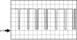
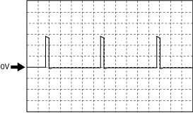
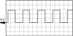
Inspection Using An Oscilloscope (Reference)
CMP (G+) signal
am6zzw00012043
|
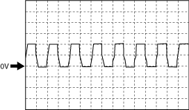
Generator output voltage
ac3wzw00005348
|
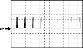
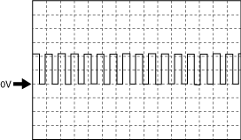
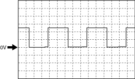
CKP (NE+) signal
am2zzw00011348
|
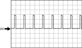
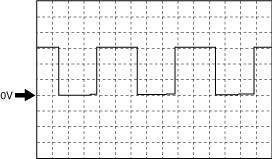
Intake shutter valve (ISV+) signal
ac3wzw00005349
|
LP-EGR control valve (LPEGR-)
atsvuw00000043
|
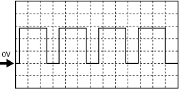
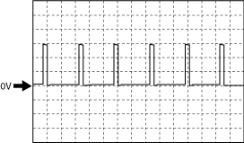
Revolution sensor signal
am3zzw00024010
|
am3zzw00024011
|
HP-EGR control valve (EGRH+)
ac3wzw00005349
|
Suction control valve signal
atsvuw00000044
|
A/F sensor heater control signal
atsvuw00000045
|
Engine oil control signal
am6zzw00012652
|
Turbocharger solenoid valve
am2zzw00011345
|
Fuel injection control (-) signal
am6zzw00012052
|
Fuel injection control (+) signal
am6zzw00012052
|
Generator field coil control signal
am3zzw00029118
|
Exhaust shutter valve (ESV+)
am3zzw00029119
|