 |
am3zzw00027713
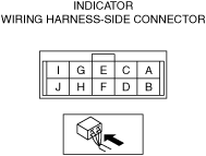
INDICATOR INSPECTION
id051800298300
1. Remove the shift panel. (See SHIFT PANEL REMOVAL/INSTALLATION.)
2. Verify that the voltages of each of the terminals are as indicated in the terminal voltage table (reference).
Terminal Voltage Table (Reference)
am3zzw00027713
|
|
Terminal |
Connected to |
Test condition |
Voltage (V) |
Inspection item(s) |
|---|---|---|---|---|
|
A
|
Battery
|
Under any condition
|
B+
|
• Wiring harness between indicator terminal A and battery positive terminal
|
|
B
|
IG1 relay No.2
|
Ignition is switched ON
|
B+
|
• Wiring harness between indicator terminal B and IG1 relay No.2 terminal C
|
|
Except above
|
Below 1.0
|
|||
|
C
|
Selector lever component (shift-lock solenoid)
|
The following conditions are met (except emergency manual shift-lock release system is operated)
― Selector lever is in P position
― Ignition is switched to ON
― Brake pedal is depressed (brake light switch is on)
|
Below 1.0
|
• Wiring harness between indicator terminal C and selector lever component terminal E
|
|
Except above
|
B+
|
|||
|
D
|
—
|
—
|
—
|
—
|
|
E
|
CAN module
|
This terminal is used for communication and cannot be used for malfunction determination during terminal voltage inspection. Perform a DTC inspection.
|
||
|
F
|
CAN module
|
This terminal is used for communication and cannot be used for malfunction determination during terminal voltage inspection. Perform a DTC inspection.
|
||
|
G
|
Selector lever component (up switch)
|
Selector lever is in the M position (+) side position.
|
Below 1.0
|
• Wiring harness between indicator terminal G and selector lever component terminal F
|
|
Selector lever is not in the M position (+) side position.
|
B+
|
|||
|
H
|
Selector lever component (down switch)
|
Selector lever is in the M position (−) side position.
|
Below 1.0
|
• Wiring harness between indicator terminal H and selector lever component terminal D
|
|
Selector lever is not in the M position (−) side position.
|
B+
|
|||
|
I
|
Selector lever component (M position switch)
|
Selector lever is in the M position.
|
Below 1.0
|
• Wiring harness between indicator terminal I and selector lever component terminal B
|
|
Selector lever is not in the M position.
|
B+
|
|||
|
J
|
Ground point
|
Under any condition
|
Approx. 0
|
• Ground point
• Wiring harness between indicator terminal J and ground point
|