|
am3zzw00037639
POWER WINDOW MAIN SWITCH INSPECTION [(E)]
id0912000021x2
Power Window Main Switch Inspection
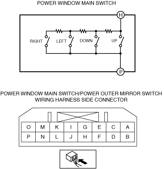
Front side switch (LF)
1. Disconnect the negative battery terminal. (See NEGATIVE BATTERY TERMINAL DISCONNECTION/CONNECTION [(E)].)
2. Remove the power window main switch. (See POWER WINDOW MAIN SWITCH REMOVAL/INSTALLATION)
3. Verify that the resistance between power window main switch terminals F and P is as indicated in the table.
am3zzw00037639
|
|
Switch Position |
Resistance (ohm) |
Terminal |
|---|---|---|
|
Auto Down
|
297.0—303.0
|
F—P
|
|
Manual Down
|
445.5—454.5
|
|
|
Auto Up
|
683.1—696.9
|
|
|
Manual Up
|
1069.2—1090.8
|
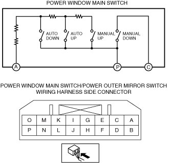
Front side switch (RF)
1. Disconnect the negative battery terminal. (See NEGATIVE BATTERY TERMINAL DISCONNECTION/CONNECTION [(E)].)
2. Remove the power window main switch. (See POWER WINDOW MAIN SWITCH REMOVAL/INSTALLATION.)
3. Verify that the resistance between power window main switch terminals A and P is as indicated in the table.
am3zzw00037640
|
|
Switch Position |
Resistance (ohm) |
Terminal |
|---|---|---|
|
Auto Down
|
445.5—454.5
|
A—P
|
|
Auto Up
|
683.1—696.9
|
|
|
Manual Up
|
1069.2—1090.8
|
4. Verify that the continuity between the power window main switch terminals is as indicated in the table.
am3zzw00037949
|
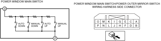
Rear side switch (LR)
1. Disconnect the negative battery terminal. (See NEGATIVE BATTERY TERMINAL DISCONNECTION/CONNECTION [(E)].)
2. Remove the power window main switch. (See POWER WINDOW MAIN SWITCH REMOVAL/INSTALLATION.)
3. Verify that the resistance between power window main switch terminals D and P is as indicated in the table.
am3zzw00037641
|
|
Switch Position |
Resistance (ohm) |
Terminal |
|---|---|---|
|
Auto Down
|
297.0—303.0
|
D—P
|
|
Manual Down
|
445.5—454.5
|
|
|
Auto Up
|
683.1—696.9
|
|
|
Manual Up
|
1069.2—1090.8
|
Rear side switch (RR)
1. Disconnect the negative battery terminal. (See NEGATIVE BATTERY TERMINAL DISCONNECTION/CONNECTION [(E)].)
2. Remove the power window main switch. (See POWER WINDOW MAIN SWITCH REMOVAL/INSTALLATION.)
3. Verify that the resistance between power window main switch terminals B and P is as indicated in the table.
am3zzw00037642
|
|
Switch Position |
Resistance (ohm) |
Terminal |
|---|---|---|
|
Auto Down
|
297.0—303.0
|
B—P
|
|
Manual Down
|
445.5—454.5
|
|
|
Auto Up
|
683.1—696.9
|
|
|
Manual Up
|
1069.2—1090.8
|
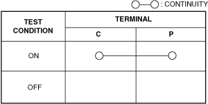
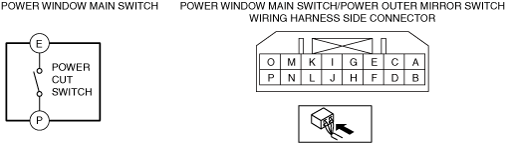
Power cut switch
1. Disconnect the negative battery terminal. (See NEGATIVE BATTERY TERMINAL DISCONNECTION/CONNECTION [(E)].)
2. Remove the power window main switch. (See POWER WINDOW MAIN SWITCH REMOVAL/INSTALLATION.)
3. Verify that the continuity between the power window main switch terminals is as indicated in the table.
am3zzw00037950
|
am3zzw00037643
|
Power Outer Mirror Switch Inspection
Up-down/left-right adjustment switch
1. Disconnect the negative battery terminal. (See NEGATIVE BATTERY TERMINAL DISCONNECTION/CONNECTION [(E)].)
2. Remove the power window main switch. (See POWER WINDOW MAIN SWITCH REMOVAL/INSTALLATION.)
3. Verify that the resistance between power window main switch terminals H and P is as indicated in the table.
am3zzw00037644
|
|
Switch Position |
Resistance (ohm) |
Terminal |
|---|---|---|
|
Up
|
0
|
H—P
|
|
Down
|
326.7—333.3
|
|
|
Left
|
999.9—1020.1
|
|
|
Right
|
2979.9—3040.1
|
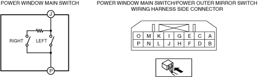
Left/right selection switch
1. Disconnect the negative battery terminal. (See NEGATIVE BATTERY TERMINAL DISCONNECTION/CONNECTION [(E)].)
2. Remove the power window main switch. (See POWER WINDOW MAIN SWITCH REMOVAL/INSTALLATION.)
3. Verify that the resistance between power window main switch terminals J and P is as indicated in the table.
am3zzw00037645
|
|
Switch Position |
Resistance (ohm) |
Terminal |
|---|---|---|
|
Left
|
0
|
J—P
|
|
Right
|
2090—2310
|
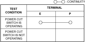
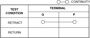
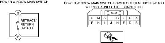
Retract/return switch
1. Disconnect the negative battery terminal. (See NEGATIVE BATTERY TERMINAL DISCONNECTION/CONNECTION [(E)].)
2. Remove the power window main switch. (See POWER WINDOW MAIN SWITCH REMOVAL/INSTALLATION.)
3. Verify that the continuity between the power outer mirror switch terminals is as indicated in the table.
am3zzw00037951
|
am3zzw00037646
|
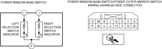
Selection switch indicator
1. Disconnect the negative battery terminal. (See NEGATIVE BATTERY TERMINAL DISCONNECTION/CONNECTION [(E)].)
2. Perform the following procedure.
am3zzw00037647
|
3. Verify that the LED is turned on.
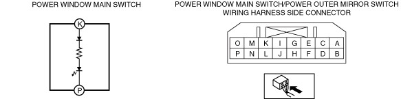
Power window switch illumination
1. Disconnect the negative battery terminal. (See NEGATIVE BATTERY TERMINAL DISCONNECTION/CONNECTION [(E)].)
2. Apply battery positive voltage to power window main switch terminal K, and connect terminal P to ground.
am3zzw00037648
|
3. Verify that the power window switch illumination turns on.