 |
ac30zw00002372
DETERMINING OPEN CIRCUIT LOCATION (CAN-BUS No.2) [(E)]
id1002x2002100
1. Verify the CAN system-related module DTCs and the module displayed in red or blue on the M-MDS screen.
2. Apply the communication error DTC and the module displayed in red or blue to the DTC output pattern and malfunctioning location, and select the possible cause for the diagnostic result and the reference for the inspection item. (See DTC Output Pattern And Malfunctioning Location)
3. Inspect the possible cause and inspection item of the applicable malfunctioning part.
DTC Output Pattern And Malfunctioning Location
|
M-MDS display |
DTC |
DTC output pattern and malfunctioning location |
||||||||||
|---|---|---|---|---|---|---|---|---|---|---|---|---|
|
DTC output module |
||||||||||||
|
PCM [SKYACTIV-G]
|
U0100:00
|
|||||||||||
|
U0121:00
|
|
|
|
|
|
×
|
|
|||||
|
U0129:00
|
|
|
|
|
|
|
|
|
|
|
|
|
|
U0131:00
|
|
|
|
|
|
|
|
|
|
|
|
|
|
U0140:00
|
|
|
|
|
|
|
|
|
|
|
|
|
|
U0151:00
|
|
|
|
|
|
|
|
|
|
|
|
|
|
U0155:00
|
|
|
|
|
|
|
|
|
|
|
|
|
|
U0164:00
|
|
|
|
|
|
|
|
|
|
|
|
|
|
U2121:00
|
|
|
|
|
|
|
|
|
|
|
|
|
|
U212E:00
|
|
|
|
|
|
|
|
|
|
|
|
|
|
U2131:00
|
|
|
|
|
|
|
|
|
|
|
|
|
|
U2133:00
|
|
|
|
|
|
|
|
|
|
|
|
|
|
PCM [SKYACTIV-X]
|
U0100:00
|
|||||||||||
|
U0121:00
|
||||||||||||
|
U0129:00
|
||||||||||||
|
U0131:00
|
||||||||||||
|
U0140:00
|
||||||||||||
|
U0151:00
|
||||||||||||
|
U0155:00
|
||||||||||||
|
U0164:00
|
||||||||||||
|
U2121:00
|
||||||||||||
|
U212E:00
|
||||||||||||
|
U2131:00
|
||||||||||||
|
U2133:00
|
||||||||||||
|
PCM [SKYACTIV-D]
|
U0101:00
|
|
|
|
|
|
|
|
|
|
|
|
|
U0121:00
|
|
|
|
|
|
×
|
||||||
|
U0131:00
|
|
|
|
|
|
|
|
|
|
|
|
|
|
U0140:00
|
|
|
|
|
|
|
|
|
|
|
|
|
|
U0151:00
|
|
|
|
|
|
|
|
|
|
|
|
|
|
U0155:00
|
|
|
|
|
|
|
|
|
|
|
|
|
|
U0164:00
|
|
|
|
|
|
|
|
|
|
|
|
|
|
U029D:00
|
|
|
|
|
|
|
|
|
×
|
|
||
|
U02A3:00
|
|
|
|
|
|
|
|
|
|
×
|
||
|
U2121:00
|
|
|
|
|
|
|
|
|
|
|
|
|
|
U212E:00
|
|
|
|
|
|
|
|
|
|
|
|
|
|
U2131:00
|
|
|
|
|
|
|
|
|
|
|
|
|
|
U2133:00
|
|
|
|
|
|
|
|
|
|
|
|
|
|
DSC HU/CM
|
U0100:00
|
×
|
|
×
|
|
×
|
|
|
|
|||
|
U0101:00
|
|
|
|
|
|
|
|
|
||||
|
U0131:00
|
|
|
|
|
|
|
|
|
||||
|
U0140:00
|
|
|
|
|
|
|
|
|
||||
|
U0151:00
|
|
|
|
|
|
|
|
|
||||
|
U0155:00
|
|
|
|
|
|
|
|
|
||||
|
U0164:00
|
|
|
|
|
|
|
|
|
|
|
|
|
|
U2121:00
|
|
|
|
|
|
|
|
|
|
|
|
|
|
U212E:00
|
|
|
|
|
|
|
|
|
|
|
|
|
|
U2131:00
|
|
|
|
|
|
|
|
|
|
|
|
|
|
EPS control module
|
U0100:00
|
×
|
|
|||||||||
|
U0121:00
|
×
|
|||||||||||
|
U0140:00
|
×
|
|||||||||||
|
U2121:00
|
||||||||||||
|
Electronically controlled brake unit
|
U0100:00
|
×
|
|
×
|
|
×
|
|
×
|
|
|
|
×
|
|
U0101:00
|
|
|
|
|
|
|
|
|
|
|
|
|
|
U0131:00
|
|
|
|
|
|
|
|
|
|
|
|
|
|
U0140:00
|
|
|
|
|
|
|
|
|
|
|
×
|
|
|
U0151:00
|
|
|
|
|
|
|
|
|
|
|
|
|
|
U0155:00
|
|
|
|
|
|
|
|
|
|
|
|
|
|
U0164:00
|
|
|
|
|
|
|
|
|
|
|
|
|
|
U2121:00
|
|
|
|
|
|
|
|
|
|
|
|
|
|
U212E:00
|
|
|
|
|
|
|
|
|
|
|
|
|
|
U2131:00
|
|
|
|
|
|
|
|
|
|
|
|
|
|
Vehicle control module (VCM)
|
U0100:00
|
×
|
|
×
|
|
×
|
|
×
|
|
|
|
×
|
|
U0101:00
|
|
|
|
|
|
|
|
|
|
|
|
|
|
U0121:00
|
|
|
|
|
|
|||||||
|
U0126:00
|
|
|
|
|
|
|
|
|
|
|
|
|
|
U0131:00
|
|
|
|
|
|
|
|
|
|
|
|
|
|
U0140:00
|
|
|
|
|
|
|
|
|
|
|
×
|
|
|
U0151:00
|
|
|
|
|
|
|
|
|
|
|
|
|
|
U0155:00
|
|
|
|
|
|
|
|
|
|
|
|
|
|
U0156:00
|
|
|
|
|
|
|
|
|
|
|
|
|
|
U0164:00
|
|
|
|
|
|
|
|
|
|
|
|
|
|
U2120:00
|
|
|
|
|
|
|
|
|
|
|
|
|
|
U2122:00
|
|
|
|
|
|
|
|
|
|
|
|
|
|
U2123:00
|
|
|
|
|
|
|
|
|
|
|
|
|
|
U2125:00
|
|
|
|
|
|
|
|
|
|
|
|
|
|
U2126:00
|
|
|
|
|
|
|
|
|
|
|
|
|
|
U212E:00
|
|
|
|
|
|
|
|
|
|
|
|
|
|
U2131:00
|
|
|
|
|
|
|
|
|
|
|
|
|
|
U2132:00
|
|
|
|
|
|
|
|
|
|
|
|
|
|
U2133:00
|
|
|
|
|
|
|
|
|
|
|
|
|
|
U2139:00
|
|
|
|
|
|
|
|
|
|
|
|
|
|
U213A:00
|
|
|
|
|
|
|
|
|
|
|
|
|
|
Body control module (BCM)
|
U0100:00
|
×
|
|
×
|
|
×
|
|
×
|
|
|
|
×
|
|
U0101:00
|
|
|
|
|
|
|
|
|
|
|
|
|
|
U0111:00
|
|
|
|
|
|
|
|
×
|
|
|
×
|
|
|
U0115:00
|
×
|
|
×
|
|
×
|
|
×
|
|
|
|
×
|
|
|
U0120:00
|
|
×
|
×
|
|
×
|
|
×
|
|
|
|
×
|
|
|
U0121:00
|
|
|
|
|
|
×
|
×
|
|
|
|
×
|
|
|
U0121:87
|
|
|
|
|
|
×
|
×
|
|
|
|
×
|
|
|
U0126:00
|
|
|
|
|
|
|
|
|
|
|
|
|
|
U0131:00
|
|
|
|
|
|
|
|
|
|
|
|
|
|
U0151:00
|
|
|
|
|
|
|
|
|
|
|
|
|
|
U0155:00
|
|
|
|
|
|
|
|
|
|
|
|
|
|
U0156:00
|
|
|
|
|
|
|
|
|
|
|
|
|
|
U0158:00
|
|
|
|
|
|
|
|
|
|
|
|
|
|
U0164:00
|
|
|
|
|
|
|
|
|
|
|
|
|
|
U0182:00
|
|
|
|
|
|
|
|
|
|
|
|
|
|
U0198:00
|
|
|
|
|
|
|
|
|
|
|
|
|
|
U0230:00
|
|
|
|
|
|
|
|
|
|
|
|
|
|
U2121:49
|
|
|
|
|
|
|
|
|
|
|
|
|
|
U212A:00
|
|
|
|
|
|
|
|
|
|
|
|
|
|
U212C:00
|
|
|
|
|
|
|
|
|
|
|
|
|
|
U212D:00
|
|
|
|
|
|
|
|
|
|
|
|
|
|
U212E:00
|
|
|
|
|
|
|
|
|
|
|
|
|
|
U2130:00
|
|
|
|
×
|
×
|
|
×
|
|
|
|
×
|
|
|
U2131:00
|
|
|
|
|
|
|
|
|
|
|
|
|
|
U2133:00
|
|
|
|
|
|
|
|
|
|
|
|
|
|
U213A:00
|
|
|
|
|
|
|
|
|
|
|
|
|
|
U213B:00
|
|
|
|
|
|
|
|
|
|
|
|
|
|
U213C:00
|
|
|
|
|
|
×
|
×
|
|
|
×
|
||
|
Connectivity master unit (CMU)
|
U0140:00
|
|
|
|
|
|
|
|
|
|
|
×
|
|
Emergency call control module
|
U0140:00
|
|
|
|
|
|
|
|
|
|
|
×
|
|
U0151:00
|
|
|
|
|
|
|
|
|
|
|
|
|
|
U0415:86
|
|
|
|
|
|
×
|
×
|
|
|
|
×
|
|
|
U213C:00
|
|
|
|
|
|
×
|
×
|
|
|
|
×
|
|
|
Auto leveling control module
|
U0122:87
|
|
|
|
|
|
×
|
×
|
|
|
|
×
|
|
U212A:87
|
|
|
|
|
|
|
|
|
|
|
|
|
|
U212B:87
|
|
|
|
|
|
|
|
|
|
|
×
|
|
|
U212D:87
|
|
|
|
|
|
|
|
|
|
|
|
|
|
Adaptive LED headlights control module
|
U0122:87
|
|
|
|
|
|
×
|
×
|
|
|
|
×
|
|
U0126:87
|
|
|
|
|
|
|
|
|
|
|
|
|
|
U0155:87
|
|
|
|
|
|
|
|
|
|
|
|
|
|
U2121:87
|
|
|
|
|
|
|
|
|
|
|
|
|
|
U212A:87
|
|
|
|
|
|
|
|
|
|
|
|
|
|
U212B:87
|
|
|
|
|
|
|
|
|
|
|
×
|
|
|
U212D:87
|
|
|
|
|
|
|
|
|
|
|
|
|
|
Dash-electrical supply unit
|
U0100:00
|
×
|
|
×
|
|
×
|
|
×
|
|
|
|
×
|
|
U0121:00
|
|
|
|
|
|
×
|
×
|
|
|
|
×
|
|
|
U0151:00
|
|
|
|
|
|
|
|
|
|
|
|
|
|
U212B:00
|
|
|
|
|
|
|
|
|
|
|
×
|
|
|
U212E:00
|
|
|
|
|
|
|
|
|
|
|
|
|
|
U2131:00
|
|
|
|
|
|
|
|
|
|
|
|
|
|
U2133:00
|
|
|
|
|
|
|
|
|
|
|
|
|
|
U213A:00
|
|
|
|
|
|
|
|
|
|
|
|
|
|
SAS control module
|
U0140:00
|
|
|
|
|
|
|
|
|
|
|
|
|
U0155:00
|
|
|
|
|
|
|
|
|
|
|
|
|
|
U0156:00
|
|
|
|
|
|
|
|
|
|
|
|
|
|
TCM
|
U0100:00
|
×
|
|
×
|
|
×
|
|
×
|
|
|
|
×
|
|
U0121:00
|
|
|
|
|
|
×
|
×
|
|
|
|
×
|
|
|
U0131:00
|
|
|
|
|
|
|
|
|
|
|
|
|
|
U0140:00
|
|
|
|
|
|
|
|
|
|
|
×
|
|
|
U0155:00
|
|
|
|
|
|
|
|
|
|
|
|
|
|
U212C:00
|
|
|
|
|
|
|
|
|
|
|
|
|
|
Integrated starter generator (ISG)
|
U0100:00
|
×
|
|
|
|
|||||||
|
Mazda M Hybrid battery
|
U0100:00
|
×
|
|
×
|
|
×
|
|
×
|
|
|
|
|
|
DC-DC converter (Mazda M Hybrid)
|
U0100:00
|
×
|
|
×
|
|
|
|
|||||
|
U212B:00
|
|
|
|
|
|
|
||||||
|
M-MDS display module
|
Module displayed in red or blue
|
|||||||||||
|
PCM
|
×
|
|
×
|
|
×
|
×
|
|
|
×
|
|||
|
Integrated starter generator (ISG)
|
|
×
|
×
|
|
×
|
×
|
|
|
×
|
|||
|
DC-DC converter (Mazda M Hybrid)
|
|
|
|
×
|
×
|
×
|
|
|
×
|
|||
|
DSC HU/CM / electronically controlled brake unit
|
|
|
|
|
|
×
|
×
|
|
|
×
|
||
|
Mazda M Hybrid battery
|
|
|
|
|
|
×
|
|
|
×
|
|||
|
NOx sensor
|
|
|
|
|
|
|
|
|
×
|
|
×
|
|
|
PM sensor
|
|
|
|
|
|
|
|
|
|
×
|
×
|
|
|
Diagnostic result
|
||||||||||||
|
Possible cause and inspection item
|
||||||||||||
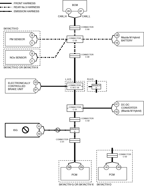
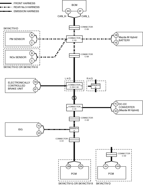
A
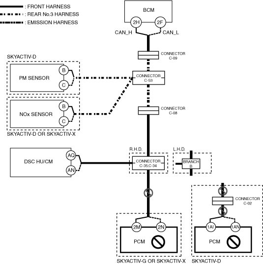
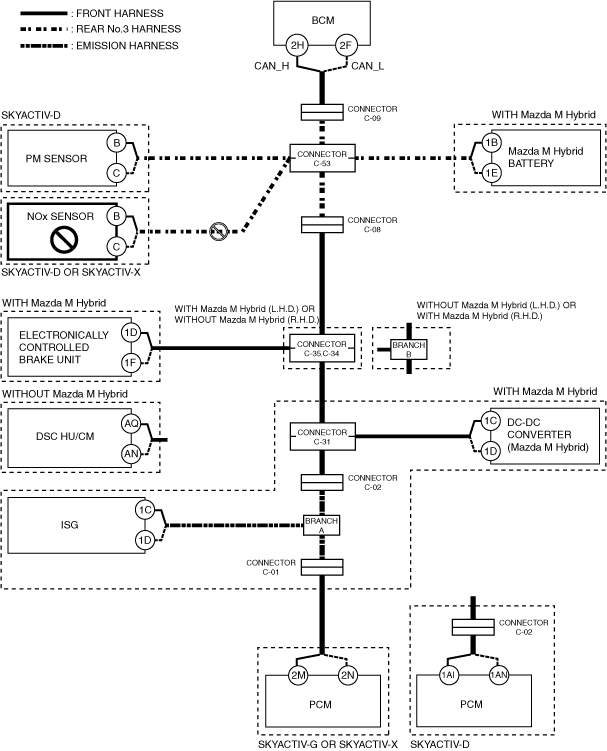
With Mazda M Hybrid
System wiring diagram
ac30zw00002372
|
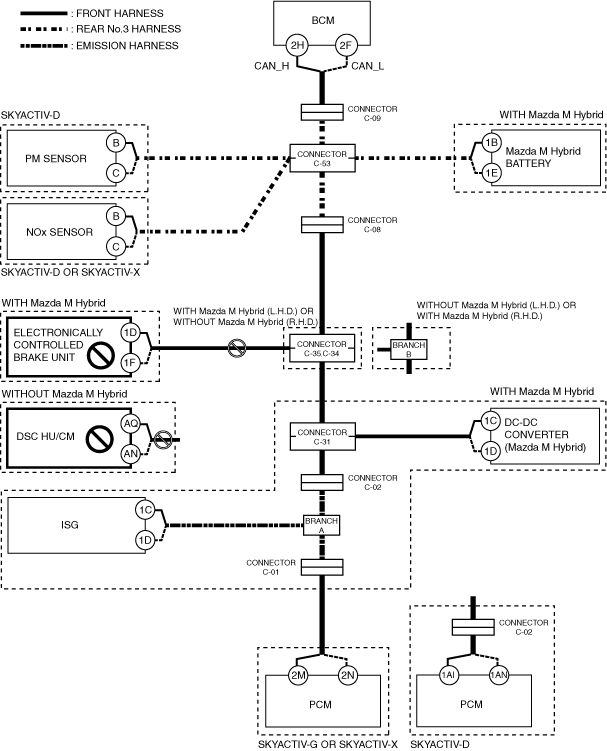
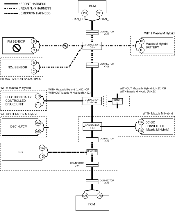
Without Mazda M Hybrid
System wiring diagram
ac30zw00002373
|
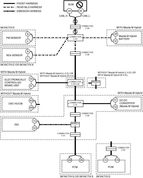
B
Possible cause
System wiring diagram
ac30zw00002374
|
Inspection item
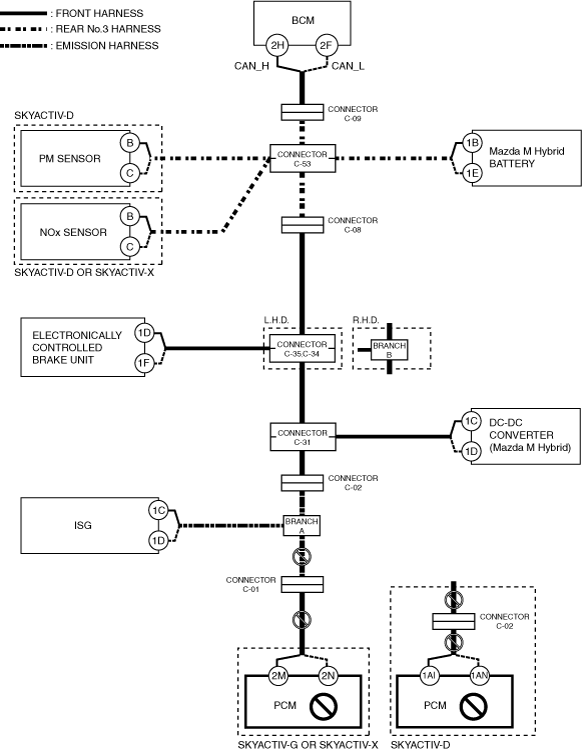
C
Possible cause
System wiring diagram
ac30zw00002375
|
Inspection item
D
Possible cause
System wiring diagram
ac30zw00002376
|
Inspection item
E
Possible cause
System wiring diagram
ac30zw00002377
|
Inspection item
F
Possible cause
System wiring diagram
ac30zw00002378
|
Inspection item
G
Possible cause
System wiring diagram
ac30zw00002379
|
Inspection item
H
Possible cause
System wiring diagram
ac30zw00002380
|
Inspection item
I
Possible cause
System wiring diagram
ac30zw00002381
|
Inspection item
J
Possible cause
System wiring diagram
ac30zw00002382
|
Inspection item
K
Possible cause
System wiring diagram
ac30zw00002383
|
Inspection item