 |
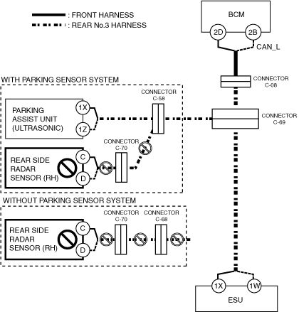
ac30zw00002414
DETERMINING OPEN CIRCUIT LOCATION (CAN-BUS No.4) [(E)]
id1002x2002900
1. Verify the CAN system-related module DTCs and the module displayed in red or blue on the M-MDS screen.
2. Apply the communication error DTC and the module displayed in red or blue to the DTC output pattern and malfunctioning location, and select the possible cause for the diagnostic result and the reference for the inspection item. (See DTC Output Pattern And Malfunctioning Location)
3. Inspect the possible cause and inspection item of the applicable malfunctioning part.
DTC Output Pattern And Malfunctioning Location
|
M-MDS display |
DTC |
DTC output pattern and malfunctioning location |
|||
|---|---|---|---|---|---|
|
DTC output module |
|||||
|
PCM [SKYACTIV-G]
|
U0100:00
|
|
|
|
|
|
U0121:00
|
|
|
|
|
|
|
U0129:00
|
|
|
|
|
|
|
U0131:00
|
|
|
|
|
|
|
U0140:00
|
|
|
|
×
|
|
|
U0151:00
|
|
|
|
|
|
|
U0155:00
|
|
|
|
|
|
|
U0164:00
|
|
|
|
|
|
|
U2121:00
|
|
|
|
|
|
|
U212E:00
|
|
|
|
|
|
|
U2131:00
|
×
|
|
|
×
|
|
|
U2133:00
|
|
|
|
|
|
|
PCM [SKYACTIV-X]
|
U0100:00
|
||||
|
U0121:00
|
|||||
|
U0129:00
|
|||||
|
U0131:00
|
|||||
|
U0140:00
|
×
|
||||
|
U0151:00
|
|||||
|
U0155:00
|
|||||
|
U0164:00
|
|||||
|
U2121:00
|
|||||
|
U212E:00
|
|||||
|
U2131:00
|
×
|
|
|
×
|
|
|
U2133:00
|
|||||
|
PCM [SKYACTIV-D]
|
U0101:00
|
|
|
|
|
|
U0121:00
|
|
|
|
|
|
|
U0131:00
|
|
|
|
|
|
|
U0140:00
|
|
|
|
×
|
|
|
U0151:00
|
|
|
|
|
|
|
U0155:00
|
|
|
|
|
|
|
U0164:00
|
|
|
|
|
|
|
U029D:00
|
|
|
|
|
|
|
U02A3:00
|
|
|
|
|
|
|
U2121:00
|
|
|
|
|
|
|
U212E:00
|
|
|
|
|
|
|
U2131:00
|
×
|
|
|
×
|
|
|
U2133:00
|
|
|
|
|
|
|
DSC HU/CM
|
U0100:00
|
|
|
|
|
|
U0101:00
|
|
|
|
|
|
|
U0131:00
|
|
|
|
|
|
|
U0140:00
|
|
|
|
×
|
|
|
U0151:00
|
|
|
|
|
|
|
U0155:00
|
|
|
|
|
|
|
U0164:00
|
|
|
|
|
|
|
U2121:00
|
|
|
|
|
|
|
U212E:00
|
|
|
|
|
|
|
U2131:00
|
×
|
|
|
×
|
|
|
EPS control module
|
U0100:00
|
|
|
|
|
|
U0121:00
|
|
|
|
|
|
|
U0140:00
|
|
|
|
×
|
|
|
U2121:00
|
|
|
|
||
|
Electronically controlled brake unit
|
U0100:00
|
|
|
|
|
|
U0101:00
|
|
|
|
|
|
|
U0131:00
|
|
|
|
|
|
|
U0140:00
|
|
|
|
×
|
|
|
U0151:00
|
|
|
|
|
|
|
U0155:00
|
|
|
|
|
|
|
U0164:00
|
|
|
|
|
|
|
U2121:00
|
|
|
|
|
|
|
U212E:00
|
|
|
|
|
|
|
U2131:00
|
×
|
|
|
×
|
|
|
Vehicle control module (VCM)
|
U0100:00
|
|
|
|
|
|
U0101:00
|
|
|
|
|
|
|
U0121:00
|
|
|
|
|
|
|
U0126:00
|
|
|
|
|
|
|
U0131:00
|
|
|
|
|
|
|
U0140:00
|
|
|
|
×
|
|
|
U0151:00
|
|
|
|
|
|
|
U0155:00
|
|
|
|
|
|
|
U0156:00
|
|
|
|
|
|
|
U0164:00
|
|
|
|
|
|
|
U2120:00
|
|
|
|
|
|
|
U2122:00
|
|
|
|
|
|
|
U2123:00
|
|
|
|
|
|
|
U2125:00
|
|
|
|
|
|
|
U2126:00
|
|
|
×
|
×
|
|
|
U212E:00
|
|
|
|
|
|
|
U2131:00
|
×
|
|
|
×
|
|
|
U2132:00
|
|
|
|
|
|
|
U2133:00
|
|
|
|
|
|
|
U2139:00
|
|
×
|
|
×
|
|
|
U213A:00
|
|
|
|
|
|
|
Body control module (BCM)
|
U0100:00
|
|
|
|
|
|
U0101:00
|
|
|
|
|
|
|
U0111:00
|
|
|
|
|
|
|
U0115:00
|
|
|
|
|
|
|
U0120:00
|
|
|
|
|
|
|
U0121:00
|
|
|
|
|
|
|
U0121:87
|
|
|
|
|
|
|
U0126:00
|
|
|
|
|
|
|
U0131:00
|
|
|
|
|
|
|
U0151:00
|
|
|
|
|
|
|
U0155:00
|
|
|
|
|
|
|
U0156:00
|
|
|
|
|
|
|
U0158:00
|
|
|
|
|
|
|
U0164:00
|
|
|
|
|
|
|
U0182:00
|
|
|
|
|
|
|
U0198:00
|
|
|
|
|
|
|
U0230:00
|
|
|
|
|
|
|
U2121:49
|
|
|
|
|
|
|
U212A:00
|
|
|
|
|
|
|
U212C:00
|
|
|
|
|
|
|
U212D:00
|
|
|
|
|
|
|
U212E:00
|
|
|
|
|
|
|
U2130:00
|
|
|
|
|
|
|
U2131:00
|
×
|
|
|
×
|
|
|
U2133:00
|
|
|
|
|
|
|
U213A:00
|
|
|
|
|
|
|
U213B:00
|
|
|
|
|
|
|
U213C:00
|
|
|
|
|
|
|
Connectivity master unit (CMU)
|
U0140:00
|
|
|
|
×
|
|
Emergency call control module
|
U0140:00
|
|
|
|
×
|
|
U0151:00
|
|
|
|
|
|
|
U0415:86
|
|
|
|
|
|
|
U213C:00
|
|
|
|
|
|
|
Auto leveling control module
|
U0122:87
|
|
|
|
|
|
U212A:87
|
|
|
|
|
|
|
U212B:87
|
|
|
|
×
|
|
|
U212D:87
|
|
|
|
|
|
|
Adaptive LED headlights control module
|
U0122:87
|
|
|
|
|
|
U0126:87
|
|
|
|
|
|
|
U0155:87
|
|
|
|
|
|
|
U2121:87
|
|
|
|
|
|
|
U212A:87
|
|
|
|
|
|
|
U212B:87
|
|
|
|
×
|
|
|
U212D:87
|
|
|
|
|
|
|
Dash-electrical supply unit
|
U0100:00
|
|
|
|
|
|
U0121:00
|
|
|
|
|
|
|
U0151:00
|
|
|
|
|
|
|
U212B:00
|
|
|
|
×
|
|
|
U212E:00
|
|
|
|
|
|
|
U2131:00
|
×
|
|
|
×
|
|
|
U2133:00
|
|
|
|
|
|
|
U213A:00
|
|
|
|
|
|
|
SAS control module
|
U0140:00
|
|
|
|
×
|
|
U0155:00
|
|
|
|
|
|
|
U0156:00
|
|
|
|
|
|
|
TCM
|
U0100:00
|
|
|
|
|
|
U0121:00
|
|
|
|
|
|
|
U0131:00
|
|
|
|
|
|
|
U0140:00
|
|
|
|
×
|
|
|
U0155:00
|
|
|
|
|
|
|
U212C:00
|
|
|
|
|
|
|
Integrated starter generator (ISG)
|
U0100:00
|
|
|
|
|
|
Mazda M Hybrid battery
|
U0100:00
|
|
|
|
|
|
DC-DC converter (Mazda M Hybrid)
|
U0100:00
|
|
|
|
|
|
U212B:00
|
|
|
|
×
|
|
|
M-MDS display module
|
Module displayed in red or blue
|
||||
|
ESU
|
×
|
|
|
×
|
|
|
Rear side radar sensor (RH)
|
|
×
|
|
×
|
|
|
Parking assist unit (ultrasonic)
|
|
|
×
|
×
|
|
|
Diagnostic result
|
|||||
|
Possible cause and inspection item
|
|||||
A
Possible cause
System wiring diagram
ac30zw00002414
|
Inspection item
B
Possible cause
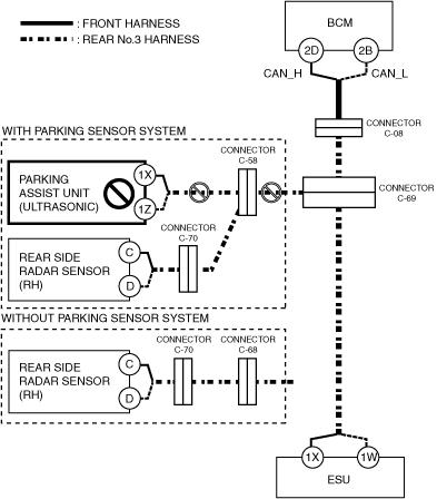
System wiring diagram
ac30zw00002415
|
Inspection item
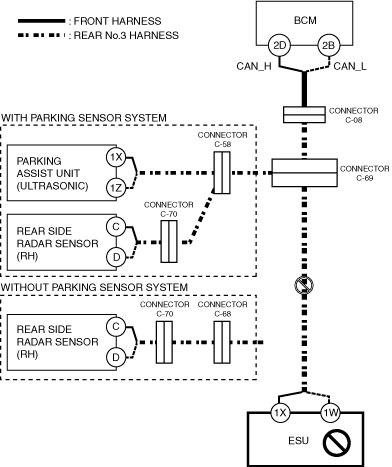
C
Possible cause
System wiring diagram
ac30zw00002416
|
Inspection item
D
Possible cause
System wiring diagram
ac30zw00002417
|
Inspection item