 |
am3zzw00030338
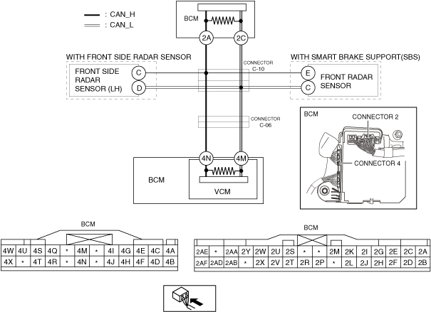
DETERMINING SHORT TO POWER SUPPLY LOCATION (CAN-BUS No.6) [(E)]
id1002x2003900
System Wiring Diagram
am3zzw00030338
|
Determination Procedure
|
Step |
Inspection |
Action |
|
|---|---|---|---|
|
1
|
INSPECT CAN LINE BETWEEN BODY CONTROL MODULE (BCM) AND CONNECTOR C-10 FOR SHORT TO POWER SUPPLY
• Switch the ignition off.
• Disconnect the negative battery terminal.
• Disconnect the connector C-10.
• Connect the negative battery terminal.
• Switch the ignition ON (engine off).
• Measure the voltage at body control module (BCM) terminals 2A and 2C.
• Is the voltage between 1.5—3.5 V?
|
Yes
|
Go to Step 3.
|
|
No
|
Go to the next step.
|
||
|
2
|
INSPECT BODY CONTROL MODULE (BCM) FOR SHORT TO POWER SUPPLY
• Switch the ignition off.
• Disconnect the negative battery terminal.
• Disconnect the connector 2 which has body control module (BCM) terminals 2A and 2C.
• Connect the connector C-10.
• Connect the negative battery terminal.
• Switch the ignition ON (engine off).
• Measure the voltage at body control module (BCM) terminals 2A and 2C (wiring harness side).
• Is the voltage between 1.5—3.5 V?
|
Yes
|
Replace the body control module (BCM) because there is a short to the power supply in the body control module (BCM).
|
|
No
|
Repair or replace the wiring harness between the body control module (BCM) and connector C-10 because the wiring harness is shorted to the power supply.
|
||
|
3
|
INSPECT CAN LINE BETWEEN REAR SIDE RADAR SENSOR (LH) AND CONNECTOR C-10 FOR SHORT TO POWER SUPPLY
• Measure the voltage at rear side radar sensor (LH) terminals C and D.
• Is the voltage between 1.5—3.5 V?
|
Yes
|
Go to Step 5.
|
|
No
|
Go to the next step.
|
||
|
4
|
INSPECT REAR SIDE RADAR SENSOR (LH) FOR SHORT TO POWER SUPPLY
• Switch the ignition off.
• Disconnect the negative battery terminal.
• Connect the connector C-10.
• Disconnect the rear side radar sensor (LH) connector.
• Connect the negative battery terminal.
• Switch the ignition ON (engine off).
• Measure the voltage at body control module (BCM) terminals 2A and 2C.
• Is the voltage between 1.5—3.5 V?
|
Yes
|
Replace the rear side radar sensor (LH) because there is a short to the power supply in the rear side radar sensor (LH).
|
|
No
|
Repair or replace the wiring harness between the rear side radar sensor (LH) and connector C-10 because the wiring harness is shorted to the power supply.
|
||
|
5
|
INSPECT CAN LINE BETWEEN FRONT RADAR SENSOR AND CONNECTOR C-10 FOR SHORT TO POWER SUPPLY
• Measure the voltage at front radar sensor terminals E and C.
• Is the voltage between 1.5—3.5 V?
|
Yes
|
Go to Step 7.
|
|
No
|
Go to the next step.
|
||
|
6
|
INSPECT FRONT RADAR SENSOR FOR SHORT TO POWER SUPPLY
• Switch the ignition off.
• Disconnect the negative battery terminal.
• Connect the connector C-10.
• Disconnect the front radar sensor connector.
• Connect the negative battery terminal.
• Switch the ignition ON (engine off).
• Measure the voltage at body control module (BCM) terminals 2A and 2C.
• Is the voltage between 1.5—3.5 V?
|
Yes
|
Replace the front radar sensor because there is a short to the power supply in the front radar sensor.
|
|
No
|
Repair or replace the wiring harness between the front radar sensor and connector C-10 because the wiring harness is shorted to the power supply.
|
||
|
7
|
INSPECT CAN LINE BETWEEN CONNECTOR C-10 AND CONNECTOR C-06 FOR SHORT TO POWER SUPPLY
• Switch the ignition off.
• Disconnect the negative battery terminal.
• Disconnect the connector C-06.
• Connect the connector C-10.
• Connect the negative battery terminal.
• Switch the ignition ON (engine off).
• Measure the voltage at body control module (BCM) terminals 2A and 2C.
• Is the voltage between 1.5—3.5 V?
|
Yes
|
Go to the next step.
|
|
No
|
Repair or replace the wiring harness between the connector C-10 and connector C-06 because the wiring harness is shorted to the power supply.
|
||
|
8
|
INSPECT CAN LINE BETWEEN CONNECTOR C-06 AND BODY CONTROL MODULE (BCM) FOR SHORT TO POWER SUPPLY
• Switch the ignition off.
• Disconnect the negative battery terminal.
• Disconnect the connector 4 which has body control module (BCM) terminals 4N and 4M.
• Connect the connector C-06.
• Connect the negative battery terminal.
• Switch the ignition ON (engine off).
• Measure the voltage at body control module (BCM) terminals 2A and 2C.
• Is the voltage between 1.5—3.5 V?
|
Yes
|
Replace the body control module (BCM) because there is a short to the power supply in the body control module (BCM).
|
|
No
|
Repair or replace the wiring harness between the connector C-06 and body control module (BCM) because the wiring harness is shorted to the power supply.
|
||