|
1
|
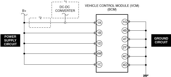
INSPECT VEHICLE CONTROL MODULE (VCM) POWER SUPPLY VOLTAGE
• Reconnect all the disconnected connectors.
• Connect the negative battery terminal.
• Measure the voltage at the following terminals.
-
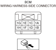
― Body control module (BCM) terminal 1A
― Body control module (BCM) terminal 1B
― Body control module (BCM) terminal 1D
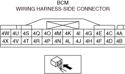
― Body control module (BCM) terminal 4W
― Body control module (BCM) terminal 1C
• Is the voltage within the standard?
|
Yes
|
Go to Step 3.
|
|
No
|
Go to the next step.
|
|
2
|
INSPECT VEHICLE CONTROL MODULE (VCM) POWER SUPPLY CIRCUIT FOR SHORT TO GROUND AND OPEN CIRCUIT
• Inspect the applicable circuit for a short to ground and an open circuit.
• Is the circuit normal?
|
Yes
|
Go to the next step.
|
|
No
|
Repair or replace the malfunctioning location and perform the repair completion verification.
|
|
3
|
INSPECT VEHICLE CONTROL MODULE (VCM) GROUND CIRCUIT FOR OPEN CIRCUIT
• Inspect the applicable circuit for an open circuit.
• Is the circuit normal?
|
Yes
|
Go to the next step.
|
|
No
|
Repair or replace the malfunctioning location and perform the repair completion verification.
|
|
Repair completion verification 1
|
VERIFY THAT VEHICLE IS REPAIRED
• Install/connect the part removed/disconnected during the troubleshooting procedure.
• Clear the DTC recorded in the memory.
• Perform the DTC inspection for the vehicle control module (VCM).
• Is the same Pending DTC present?
|
Yes
|
Refer to the controller area network (CAN) malfunction diagnosis flow to inspect for a CAN communication error.
If the CAN communication is normal, perform the diagnosis from Step 1.
• If the malfunction recurs, replace the body control module (BCM), then go to the next step.
|
|
No
|
Go to the next step.
|
|
Repair completion verification 2
|
VERIFY IF OTHER DTC IS DISPLAYED
• Perform the DTC inspection.
• Are any other DTCs displayed?
|
Yes
|
Repair the malfunctioning location according to the applicable DTC troubleshooting.
|
|
No
|
DTC troubleshooting completed.
|