|
bmcozp00000520
DIAGNOSTIC ASSIST FUNCTION [CONNECTIVITY MASTER UNIT (E)]
id1602a10096a4
Activation Procedure
1. Switch the ignition to ACC or ON (engine off or on).
2. Press the following buttons simultaneously for 3 s or more while pressing the VOLUME knob on the commander switch, with the center display displayed.
bmcozp00000520
|
azzjjw00001925
|
3. The diagnostic assist function initial screen is displayed on the center display and the diagnostic assist function launches.
Ending Procedure
1. Select [End Diag Mode] on the diagnostic assist function initial screen and wait for 10 s or more.
2. The diagnostic assist function ends and the center display initial screen launches.
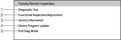
Diagnostic Assist Function Initial Screen
bmcozp00000001
|
|
No. |
Indication on center display |
Content/function |
|---|---|---|
|
1
|
Diagnostic Test
|
Performs troubleshooting for the connectivity master unit (CMU) and nearby devices.
|
|
2
|
Functional Inspection/Adjustment
|
Performs inspection of each function and adjustment of the settings.
|
|
3
|
Service Information
|
Backs-up user information and displays device information.
|
|
4
|
Device Program Update
|
Updates the programs for each device.
|
|
5
|
End Diag Mode
|
Ends the diagnostic assist function.
|
Diagnostic Assist Function Table
|
Indication on center display |
Content/reference |
||
|---|---|---|---|
|
Diagnostic Test
|
System Self-Diagnostic Test
|
System Self-Diagnostic Test Result
|
Verifies diagnostic results for each target device classification
|
|
Clear DTC
|
Clears the DTCs stored by the connectivity master unit (CMU) and nearby devices.
(See DTC clearing.)
|
||
|
Settings/Registered Information Initialization
|
Perform initialization for all the data (such as user data and each type of setting).
|
||
|
Vehicle Signal Status
|
Verifies the condition of each vehicle signal.
|
||
|
Diagnostic Record Collection
|
Displays on the center display, but does not operate.
|
||
|
Storage Diagnostic Test
|
Performs diagnostics for each storage.
(See Storage diagnosis.)
|
||
|
Antenna Connection Status
|
Verifies the connection status of each antenna.
|
||
|
Vehicle Information
|
Verifies each vehicle information.
|
||
|
Vehicle Signal (Unit Status)
|
Verifies the connection status of nearby devices and availability of equipment.
|
||
|
Functional Inspection/Adjustment
|
Steering SW Inspection
|
Inspect the steering switch.
(See Steering switch inspection.)
|
|
|
Touch Pad/Commander Inspection
|
Inspect the commander switch.
(See Commander switch inspection.)
|
||
|
Microphone Inspection
|
Inspect the microphone.
(See Microphone inspection.)
|
||
|
Navigation System Inspection*1
|
Inspect the navigation function.
|
||
|
Vehicle Signal Information
|
Verifies each vehicle signal information.
|
||
|
DTV Reception Inspection
|
Displays on the center display, but does not operate.
|
||
|
Sound Library Setting
|
Verifies the sound library settings.
|
||
|
Hands-free Sound Quality Setting
|
Displays on the center display, but does not operate.
|
||
|
DAB Reception Inspection*2
|
Verifies the DAB reception condition.
|
||
|
CD Test*3
|
Inspects CD player or DVD/CD player.
|
||
|
Radio Test Mode AM
|
Verifies AM radio information.
|
||
|
Radio Test Mode FM
|
Verifies FM radio information.
|
||
|
Active Speaker Check Function
|
Inspects each speaker.
(See Speaker inspection.)
|
||
|
SiriusXM Authentication
|
Displays on the center display, but does not operate because item is for manufacturer use.
|
||
|
HD Recognition
|
Displays on the center display, but does not operate.
|
||
|
DAB Status*2
|
Verifies DAB status.
(See DAB status verification.)
|
||
|
Display Test
|
Inspects the display.
(See Display inspection.)
|
||
|
AM/FM Radio Diagnostics
|
Displays on the center display, but does not operate because item is for developer use.
|
||
|
Service Information
|
Connected Device Information
|
Verifies information for each connected device.
|
|
|
Backup Restore
|
Connectivity master unit (CMU) information takeover
(See Backup restore.)
|
||
|
Personal Information Deletion
|
Deletes personal information.
|
||
|
TCU Linked Information
|
Displays on the center display, but does not operate.
|
||
|
Communication Restricted Mode
|
Displays on the center display, but does not operate.
|
||
|
Helpnet/TCU Information
|
Displays on the center display, but does not operate.
|
||
|
Helpnet History
|
Displays on the center display, but does not operate.
|
||
|
Device Program Update
|
Owner’s Manual Update
|
How to install the OM data into vehicle.
|
|
Diagnostic Test Menu
On-board diagnostic result verification
1. Launch the diagnostic assist function. (See Activation Procedure.)
2. Select in the following order from the diagnostic assist function initial screen.
3. Select the applicable device and verify the on-board diagnostic result.
|
Diagnostic target device classification |
Diagnostic target device |
|
|---|---|---|
|
Indication on center display |
Indication on center display |
Part name/content |
|
Inspection of Device Connected via MOST
|
CMU
|
Connectivity master unit (CMU)
|
|
RT
|
Remote tuner (RT)
|
|
|
AMP
|
Audio amplifier
|
|
|
Inspection of Device Connected via GMSL
|
DISP
|
Center display
|
|
RSES
|
Displays on the center display, but does not operate.
|
|
|
HUB
|
Displays on the center display, but does not operate.
|
|
|
Inspection of Device Connected via USB
|
DECK*
|
CD player or DVD/CD player
|
|
DSRC
|
Displays on the center display, but does not operate.
|
|
|
Inspection of Device Connected via Other Method
|
COMMANDER
|
Commander switch
|
|
MIC
|
Microphone
|
|
Diagnostic target device classification screen/diagnostic target device screen
bmcozp00000002
|
|
No. |
Name |
Content |
|---|---|---|
|
1
|
Diagnostic target device classification
|
Displays the type of diagnostic target device (MOST connected device,/GMSL connected device/USB connected device/other connected devices).
|
|
2
|
Diagnostic result
|
Displays the diagnostic results of each diagnostic target device.
• [Not connected]: Diagnostic target device is not connected
• [No response:]: No response from diagnostic target device
• [Details]: Switches to diagnostic target device screen
• [OK]: Other than above
|
|
3
|
Diagnostic target device
|
Displays the diagnostic target device.
|
|
4
|
DTC clear button
|
Clears the DTC of the displayed diagnostic target device.
|
|
5
|
Occurrence time
|
Displays the occurrence time of the applicable DTC.
|
|
6
|
DTC No.
|
Displays up to 6 DTCs of the displayed diagnostic target devices.
|
4. If a DTC is displayed, repair the malfunctioning location according to the DTC troubleshooting.
5. Ends the diagnostic assist function. (See Ending Procedure.)
DTC clearing
1. Launch the diagnostic assist function. (See Activation Procedure.)
2. Select in the following order from the diagnostic assist function initial screen.
3. Clear the DTCs stored in the connectivity master unit (CMU) and nearby devices according to the directions on the screen.
4. Ends the diagnostic assist function. (See Ending Procedure.)
Settings/programmed information initialization
1. Launch the diagnostic assist function. (See Activation Procedure.)
2. Select in the following order from the diagnostic assist function initial screen.
3. Perform initialization for each type of setting and programmed information according to the directions on the screen.
4. The diagnostic assist function ends and the center display initial screen launches.
Vehicle signal status verification
1. Launch the diagnostic assist function. (See Activation Procedure.)
2. Select in the following order from the diagnostic assist function initial screen.
3. Verify the following vehicle signal status.
|
Indication on center display |
Unit |
Content |
|---|---|---|
|
Vehicle Speed
|
km/h
|
Displays the value of the vehicle speed signal received by the connectivity master unit (CMU).
|
|
PKB
|
ON/OFF
|
Displays the value of the parking brake status signal received by the connectivity master unit (CMU).
|
|
REV
|
ON/OFF
|
Displays the value of the R position status signal (ATX)/reverse status signal (MTX) received by the connectivity master unit (CMU).
|
|
TAIL
|
ON/OFF
|
Displays the value of the TNS (parking lights) on status signal received by the connectivity master unit (CMU).
|
|
Navi Version*
|
—
|
Displays the version of the navigation function.
|
|
Navi Manufacture*
|
—
|
Displays the navigation function manufacturer and market (JAPAN/GLOBAL).
|
4. Ends the diagnostic assist function. (See Ending Procedure.)
Storage diagnosis
1. Launch the diagnostic assist function. (See Activation Procedure.)
2. Select in the following order from the diagnostic assist function initial screen.
3. Select the applicable storage and perform the diagnostic test for the storage.
|
Indication on center display |
Diagnostic result |
Content/action |
|---|---|---|
|
OS/APP Areas
|
OK
|
No problem with OS/application area storage
|
|
NG
|
Malfunction in OS/application area storage (connectivity master unit (CMU) malfunction)
• Inspect the following:
|
|
|
CD Ripping Area
|
Displays on the center display, but does not operate.
|
|
|
MAP Areas*
|
OK
|
No problem with map area storage
|
|
NG
|
Malfunction in map area storage (malfunction with SD card inserted into USB port/SD card slot hub)
• Inspect the following:
|
|
4. Ends the diagnostic assist function. (See Ending Procedure.)
Antenna connection status verification
1. Launch the diagnostic assist function. (See Activation Procedure.)
2. Select in the following order from the diagnostic assist function initial screen.
3. Verify the connection status of each antenna according to the following table.
|
Indication on center display |
Diagnostic result |
Content/action |
|
|---|---|---|---|
|
AM/FM
|
Antenna 1
|
Connected
|
No problem
|
|
Open
|
Open circuit in antenna amplifier power supply circuit
• Inspect the following:
|
||
|
Short
|
Short circuit in antenna amplifier power supply circuit
• Inspect the following:
|
||
|
—
|
Not equipped with glass antenna
|
||
|
AM/FM
|
Antenna 2
|
Connected
|
No problem
|
|
Open
|
Open circuit in antenna amplifier power supply circuit
• Inspect the following:
|
||
|
Short
|
Short circuit in antenna amplifier power supply circuit
• Inspect the following:
|
||
|
—
|
Not equipped with glass antenna
|
||
|
DTV
|
Antenna 1
|
—
|
Because it is not equipped, [—] is constantly displayed.
|
|
Antenna 2
|
—
|
Because it is not equipped, [—] is constantly displayed.
|
|
|
Antenna 3
|
—
|
Because it is not equipped, [—] is constantly displayed.
|
|
|
Antenna 4
|
—
|
Because it is not equipped, [—] is constantly displayed.
|
|
|
DAB*1
|
Antenna 1
|
Connected
|
No problem
|
|
Open
|
Open circuit in glass antenna circuit
• Inspect the following:
|
||
|
Short
|
Short circuit in glass antenna circuit
• Inspect the following:
|
||
|
—
|
Not equipped with glass antenna
|
||
|
Antenna 2
|
—
|
Because it is not equipped, [—] is constantly displayed.
|
|
|
SiriusXM
|
Antenna 1
|
—
|
Because it is not equipped, [—] is constantly displayed.
|
4. Ends the diagnostic assist function. (See Ending Procedure.)
Vehicle information verification
1. Launch the diagnostic assist function. (See Activation Procedure.)
2. Select in the following order from the diagnostic assist function initial screen.
3. Verify the following vehicle information.
|
Indication on center display |
Unit |
Content |
|---|---|---|
|
Android_Auto
|
None/Equipped/Reserved/Invalid
|
Displays the availability of equipment for Android AutoTM.
|
|
ASE_SYSTEM
|
None/Equipped/Reserved/Invalid
|
Displays the availability of equipment for approaching vehicle audible system.
|
|
B_CALL
|
None/JAPAN/USA/CANADA/Reserved/Invalid
|
Displays the availability of equipment for bCall.
|
|
BEV_MAINTENANCE_LIMIT
|
NONE/10000KM/730DAYS/15000KM/730DAYS/16000KM/730DAYS/8000KM/183DAYS/10000KM/183DAYS/10000KM/365DAYS/12000KM/365DAYS/15000KM/365DAYS/16000KM/365DAYS/20000KM/365DAYS/20000KM/730DAYS/12000KM/730DAYS/30000KM/365DAYS/Reserved
|
Displays the maintenance setting status of the EV system.
|
|
BODY
|
Sedan/Wagon/Hatch_Back/Open_Car/Reserved/Invalid
|
Displays the body style.
|
|
BRAND
|
Mazda/OEM_A/OEM_B/Reserved/Invalid
|
Displays the brand (maker).
|
|
Carplay
|
None/Equipped/Reserved/Invalid
|
Displays the availability of equipment for Apple CarPlayTM.
|
|
CD_Player
|
None/Equipped/Reserved/Invalid
|
Displays the availability of equipment for CD player.
|
|
CD_Ripping
|
None/Equipped/Reserved/Invalid
|
Displays the availability of equipment for CD ripping.
|
|
CMU_Spec
|
None/Taiwan/China/Reserved/Other/Invalid
|
Displays the specification of the connectivity master unit (CMU).
|
|
Commander_Touchpad
|
None/Equipped/Reserved/Invalid
|
Displays the availability of equipment for touch pad of the commander switch.
|
|
DAB
|
None/Equipped/Reserved/Invalid
|
Displays whether or not DAB radio is compatible.
|
|
DISPLAY_SIZE
|
8.8 inch/10.25 inch/Reserved/Invalid
|
Displays the size of a display and availability of equipment.
|
|
DRIVE
|
2WD/4WD/Reserved/Invalid
|
Displays the drive type.
|
|
DRIVER_ATTENTION_ALERT
|
None/Equipped/Reserved/Invalid
|
Displays the availability of equipment for driver attention alert system.
|
|
DRIVER_MONITOR
|
None/Equipped/Reserved/Invalid
|
Displays the availability of equipment for driver monitor system.
|
|
DVD_Player
|
None/Equipped/Reserved/Invalid
|
Displays the availability of equipment for DVD/CD player.
|
|
ELK_CUSTOMIZE_TYPE
|
Type-A/Type-B(NCAP)/Reserved/Invalid
|
Displays the type of emergency lane keeping (ELK) and availability of equipment.
|
|
EMERGENCY_CALL
|
None/RUSSIA_ECALL/US_ECALL/EU_ECALL/OTHER_ECALL/JPN_ECALL/ADR_ECALL/MALAYSIA_ECALL/GULF_ECALL/Reserved/Invalid
|
Displays the type of emergency call system and availability of equipment.
|
|
ENGINE
|
Petrol_Engine/Diesel_Engine/HEV/BEV/Reserved/Invalid
|
Displays the type of engine.
|
|
F_SEAT_TYPE
|
Standard/Recaro/Others/Reserved/Invalid
|
Displays the type of front seats.
|
|
FREQUENCY
|
None/9/100kHz_Pitch/5/100kHz_Pitch/10/200kHz_Pitch/9/50kHz_Pitch/Others/Reserved/Invalid
|
Displays the type of frequency.
|
|
FRONT_RADAR
|
None/Equipped/Reserved/Invalid
|
Displays the availability of equipment for front radar sensor.
|
|
HDMI
|
None/Equipped/Reserved/Invalid
|
Displays whether or not HDMI is compatible.
|
|
HEAD_UP_DISPLAY
|
None/Equipped/Reserved/Invalid
|
Displays the availability of equipment for active driving display.
|
|
I_DM
|
None/Equipped/Reserved/Invalid
|
Displays the availability of equipment for intelligent drive master (i-DM).
|
|
I_STOP_TYPE
|
None/Normal_Start_Stop/Expanded_Start_Stop/Reserved/Invalid
|
Displays the type of i-stop and availability of equipment.
|
|
Limit_Of_DAB_Range
|
None/Equipped/Reserved/Invalid
|
Displays whether or not DAB radio tuning range limitation function is equipped.
|
|
LW
|
None/Equipped/Reserved/Invalid
|
Displays whether or not AM radio LW frequency band can be received.
|
|
Microphone
|
Array/ECALL/Reserved/Invalid
|
Displays the type of microphone.
|
|
Mobile_911
|
None/Equipped/Reserved/Invalid
|
Displays the availability of equipment for Mobile-911.
|
|
MULTI_DOT_DISPLAY
|
None/Equipped/Reserved/Invalid
|
Displays the availability of equipment for multi-information display.
|
|
Number_Of_Seat_Rows
|
2_Rows/3_Rows/Reserved/Invalid
|
Displays the number of seat rows.
|
|
OVER_HEAD_CONSOLE
|
None/Equipped(With_Sunglass_Holder)/Equipped(Without_Sunglass_Holder)/Others/Reserved/Invalid
|
Displays the type of overhead console and availability of equipment.
|
|
Pandora
|
None/Equipped/Reserved/Invalid
|
Displays the availability of equipment for Pandora radio.
|
|
PARKING_SENSOR
|
None/Front(Corner)/F&R(Corner&Center)/Rear(Corner&Center)/Reserved/Invalid
|
Displays the type of ultrasonic sensor and availability of equipment.
|
|
Project_Code_1st—Project_Code_4th
|
Invalid
|
Displays the project code.
|
|
RDS
|
None/Equipped/Reserved/Invalid
|
Displays the availability of equipment for RDS.
|
|
REAR_SIDE_RADAR
|
None/Equipped/Reserved/Invalid
|
Displays the availability of equipment for rear side radar sensor.
|
|
REGENERATION_TYPE
|
None/i-ELOOP/Mild_HEV_Without_Coasting/Mild_HEV_With_Coasting/Reserved/Invalid
|
Displays the type of i-ELOOP and availability of equipment.
|
|
ROOF
|
Standard/Sun_Roof/Soft_Top/RHT/Reserved/Invalid
|
Displays the type of roof.
|
|
RSES
|
None/Equipped/Reserved/Invalid
|
Displays the availability of equipment for rear seat entertainment system (RSES).
|
|
SATELITE_SPEC
|
None/USA/Canada/Reserved/Invalid
|
Displays the type of satellite.
|
|
SEAT_MATERIAL
|
Cloth/Leatherette/Leather/Leatherette&Cloth/Others/Reserved/Invalid
|
Displays the material of the seat.
|
|
SPEAKER_TYPE
|
None/Standard_SP6/Standard_SP8/High_Grade_Bose_SP12/Others/Reserved/Invalid
|
Displays the type of speaker and availability of equipment.
|
|
Steering_Position
|
LHD/RHD/Reserved/Invalid
|
Displays the steering wheel specification.
|
|
TELEMATICS_COM_UNIT
|
None/Equipped/Reserved/Invalid
|
Displays the availability of equipment for telematics communication system.
|
|
TRANSMISSION
|
MT/AT/HEV/Reserved/Invalid
|
Displays the type of transmission/transaxle.
|
|
Tuner_AM_Range
|
None/Wide/Reserved/Invalid
|
Displays the type of AM tuner (remote tuner (RT)) and availability of equipment.
|
|
TV_TUNER
|
None/Equipped/Reserved/Invalid
|
Displays the availability of equipment for TV tuner (remote tuner (RT)).
|
|
Unit_Destination
|
JPN/ADR/UK/CHN/EU/Gen;L/US/Gen;R/Invalid
|
Displays the destination.
|
|
Vehicle_Height
|
0-65534mm/Invalid
|
Displays the overall height of the vehicle.
|
|
Vehicle_Length
|
0-65534mm/Invalid
|
Displays the overall length of the vehicle.
|
|
Vehicle_Width
|
0-65534mm/Invalid
|
Displays the overall width of the vehicle.
|
|
VIEW_MONITOR_CAMERA
|
None/Rear_Without_ECU/Rear_With_ECU/Front&Rear_With_ECU/Side(P_Only)&Rear_With_ECU/Front&Side&Rear_With_ECU/Reserved/Invalid
|
Displays the type of camera and availability of equipment.
|
|
VIN
|
—
|
Displays the Vehicle Identification Number (VIN).
|
|
EngineDisplacement
|
—
|
Displays the engine displacement.
|
4. Ends the diagnostic assist function. (See Ending Procedure.)
Nearby device connection condition and equipment verification
1. Launch the diagnostic assist function. (See Activation Procedure.)
2. Select in the following order from the diagnostic assist function initial screen.
3. Verify the following information.
|
Indication on center display |
Diagnostic result |
Content |
|---|---|---|
|
AMP
|
OK
|
Audio amplifier related DTCs are not stored.
|
|
NG
|
Audio amplifier related DTCs are stored.
|
|
|
MIC
|
OK
|
Microphone related DTCs are not stored.
|
|
NG
|
Microphone related DTCs are stored.
|
|
|
DECK
|
Equipped-OK
|
CD player or DVD/CD player related DTCs are not stored.
|
|
Equipped-NG
|
CD player or DVD/CD player related DTCs are stored.
|
|
|
Not Equipped
|
Not equipped with CD player or DVD/CD player
|
|
|
HUB
|
OK
|
USB port/SD card slot hub related DTCs are not stored.
|
|
NG
|
USB port/SD card slot hub related DTCs are stored.
|
|
|
RSE
|
Equipped-OK
|
Displays on the center display, but does not operate.
|
|
Equipped-NG
|
||
|
Not Equipped
|
||
|
NAVI
|
Equipped-OK
|
Valid SD card is inserted.
|
|
Equipped-NG
|
Valid SD card is not inserted.
|
|
|
Not Equipped
|
Not equipped with navigation function
|
|
|
COMMANDER
|
OK
|
Commander switch related DTCs are not stored.
|
|
NG
|
Commander switch related DTCs are stored.
|
|
|
Camera
|
Equipped-OK
|
Rear mount camera related DTCs are not stored.
|
|
Equipped-NG
|
Rear mount camera related DTCs are stored.
|
|
|
Not Equipped
|
Not equipped with rear mount camera
|
|
|
C-BCM
|
OK
|
Body control module (BCM) related DTCs are not stored.
|
|
NG
|
Body control module (BCM) related DTCs are stored.
|
|
|
RT
|
OK
|
Remote tuner (RT) related DTCs are not stored.
|
|
NG
|
Remote tuner (RT) related DTCs are stored.
|
|
|
CenterDisplay
|
OK
|
Center display related DTCs are not stored.
|
|
NG
|
Center display related DTCs are stored.
|
|
|
ST-SW
|
OK
|
Steering switch related DTCs are not stored.
|
|
NG
|
Steering switch related DTCs are stored.
|
|
|
GPS
|
OK
|
Global Navigation Satellite System (GNSS) antenna/global positioning system (GPS) antenna related DTCs are not stored.
|
|
NG
|
Global Navigation Satellite System (GNSS) antenna/global positioning system (GPS) antenna related DTCs are stored.
|
|
|
Satellite Antenna (SXM)
|
Equipped-OK
|
Antenna amplifier related DTCs are not stored.
|
|
Equipped-NG
|
Antenna amplifier related DTCs are stored.
|
|
|
Not Equipped
|
Not equipped with antenna amplifier
|
4. Ends the diagnostic assist function. (See Ending Procedure.)
Functional Inspection/Adjustment Menu
Steering switch inspection
1. Launch the diagnostic assist function. (See Activation Procedure.)
2. Select in the following order from the diagnostic assist function initial screen.
3. Verify if the indication on the center display changes correctly in conjunction with the steering switch operation.
|
Steering switch operation |
Indication on center display |
Action |
|---|---|---|
|
Volume adjustment button (-) is pressed
|
Vol. down SW Pressed
|
Inspect the following if the indication on the center display does not operate correctly in conjunction with the steering switch operation.
• Steering switch related DTCs
• Steering switch related symptom troubleshooting
• Steering switch
(Refer to [STEERING SWITCH INSPECTION] in workshop manual)
• Clock spring
(Refer to [CLOCK SPRING INSPECTION] in workshop manual)
• Wiring harness between steering switch and connectivity master unit (CMU)
|
|
Volume adjustment button (-) is released from it pressed
|
Vol. down SW Released
|
|
|
Volume adjustment button (+) is pressed
|
Vol. up SW Pressed
|
|
|
Volume adjustment button (+) is released
|
Vol. up SW Released
|
|
|
SEEK (+) switch is pressed
|
→ SW Pressed
|
|
|
SEEK (+) switch is released
|
→ SW Released
|
|
|
SEEK (-) switch is pressed
|
← SW Pressed
|
|
|
SEEK (-) switch is released
|
← SW Released
|
|
|
MUTE button is pressed
|
Mute SW Pressed
|
|
|
MUTE button is released
|
Mute SW Released
|
|
|
PICK-UP button is pressed
|
Pick-up SW Pressed
|
|
|
PICK-UP button is released
|
Pick-up SW Released
|
|
|
HANG-UP button is pressed
|
Hang-up SW Pressed
|
|
|
HANG-UP button is released
|
Hang-up SW Released
|
|
|
SOURCE button is pressed
|
Source SW Pressed
|
|
|
SOURCE button is released
|
Source SW Released
|
4. Ends the diagnostic assist function. (See Ending Procedure.)
Commander switch inspection
1. Launch the diagnostic assist function. (See Activation Procedure.)
2. Select in the following order from the diagnostic assist function initial screen.
3. Verify if the indication on the center display changes correctly in conjunction with the commander switch operation.
|
Commander switch operation |
Indication on center display |
Action |
||
|---|---|---|---|---|
|
Operation SW |
Touch Pad Inspection/Operation |
Commander Inspection/Operation |
||
|
Commander knob touch pad is touched
|
—
|
Touch
|
—
|
Inspect the following if the indication on the center display does not operate correctly in conjunction with the commander switch operation.
• Commander switch related DTCs
• Commander switch related symptom troubleshooting
• Wiring harness between commander switch and connectivity master unit (CMU)
|
|
Commander knob touch pad is released
|
Release
|
|||
|
Commander knob is pressed
|
Commander
|
—
|
Press
|
|
|
Commander knob is released
|
Release
|
|||
|
Commander knob is rotated clockwise
|
Right Turn
|
|||
|
Commander knob is rotated counterclockwise
|
Left Turn
|
|||
|
Commander knob is tilted up
|
Tilt Up
|
|||
|
Commander knob is tilted down
|
Tilt Down
|
|||
|
Commander knob is tilted right
|
Right Tilt
|
|||
|
Commander knob is tilted left
|
Left Tilt
|
|||
|
Commander knob is tilted diagonally to upper right
|
Right Tilt Up
|
|||
|
Commander knob is tilted diagonally to lower right
|
Right Tilt Down
|
|||
|
Commander knob is tilted diagonally to upper left
|
Left Tilt Up
|
|||
|
Commander knob is tilted diagonally to lower left
|
Left Tilt Down
|
|||
|
HOME button is pressed
|
HOME
|
—
|
Press
|
|
|
HOME button is released
|
Release
|
|||
|
ENTERTAINMENT button is pressed
|
Entertainment
|
—
|
Press
|
|
|
ENTERTAINMENT button is released
|
Release
|
|||
|
MAP button is pressed
|
Navi
|
—
|
Press
|
|
|
MAP button is released
|
Release
|
|||
|
FAVORITES button is pressed
|
Favorite
|
—
|
Press
|
|
|
FAVORITES button is released
|
Release
|
|||
|
VOLUME knob is pressed
|
Volume
|
—
|
Press
|
|
|
VOLUME knob is released
|
Release
|
|||
|
VOLUME knob is rotated clockwise
|
Right Turn
|
|||
|
VOLUME knob is rotated counterclockwise
|
Left Turn
|
|||
4. Ends the diagnostic assist function. (See Ending Procedure.)
Microphone inspection
1. Launch the diagnostic assist function. (See Activation Procedure.)
2. Select in the following order from the diagnostic assist function initial screen.
3. Verify if the microphone input status is displayed correctly, or the record and playback function operate correctly.
Microphone inspection screen
bmcozp00000003
|
|
No. |
Name |
Content/function |
Action |
|---|---|---|---|
|
1
|
Microphone input level
|
The microphone input level is indicated in 8 levels.
|
Inspect the following if the microphone does not operate correctly.
• Microphone related DTCs
• Microphone related symptom troubleshooting
• Wiring harness between microphone and connectivity master unit (CMU)
|
|
2
|
Record button
|
Record audio input from the microphone for 5 s.
|
|
|
3
|
Stop button
|
Stop recording or playback.
|
|
|
4
|
Playback button
|
Playback the recorded audio.
|
|
|
5
|
—
|
[REC] is indicated while recording.
|
4. Ends the diagnostic assist function. (See Ending Procedure.)
Navigation function inspection
1. Launch the diagnostic assist function. (See Activation Procedure.)
2. Select in the following order from the diagnostic assist function initial screen.
3. Verify if the navigation function is operating correctly referring to the following table.
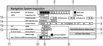
Navigation function inspection screen
bmcozp00000004
|
|
No. |
Name |
Indication on center display |
Content/function |
Action |
|---|---|---|---|---|
|
1
|
Positioning level
|
OK (3D)
|
The connectivity master unit (CMU) receives information from 4 or more GNSS satellites and indicates that 3D positioning is operative.
|
Inspect the following if the navigation function does not operate correctly.
• Global Navigation Satellite System (GNSS) antenna or global positioning system (GPS) antenna related DTCs
• Global Navigation Satellite System (GNSS) antenna or global positioning system (GPS) antenna related symptom troubleshooting
• GPS antenna feeder
(Refer to [GPS ANTENNA FEEDER INSPECTION] in workshop manual)
• Global Navigation Satellite System (GNSS) antenna
(Refer to [GLOBAL NAVIGATION SATELLITE SYSTEM (GNSS) ANTENNA INSPECTION] in workshop manual)
• Wiring harness between Global Navigation Satellite System (GNSS) antenna/global positioning system (GPS) antenna and connectivity master unit (CMU)
|
|
OK (2D)
|
The connectivity master unit (CMU) receives information from 3 GNSS satellites and indicates that 2D positioning is operative.
|
|||
|
NG
|
The connectivity master unit (CMU) receives information from only 2 or less GNSS satellites and indicates that positioning cannot be calculated.
|
|||
|
Error
|
Indicates that a reception error has occurred.
|
|||
|
-
|
Other
|
|||
|
2
|
GNSS reception number
|
—
|
Indicates the number of GNSS receptions up to 12 satellites.
|
|
|
3
|
2D positioning time
|
%
|
Indicates the percentage of time the positioning level indicates that 2D positioning is operative.
|
|
|
4
|
Positioning level NG time
|
%
|
Indicates the percentage of time the positioning level indicates NG.
|
|
|
5
|
Current position (longitude)
|
° (deg) ’”
|
Indicates the current longitudinal position in [degrees], [minutes], and [seconds].
|
|
|
6
|
Relative bearing/relative angle reset
|
Reset Relative Bearing/Relative Angle
|
Resets the relative bearing and relative angle.
|
|
|
7
|
GNSS date and time setting
|
GPS Date/Time Setting
|
Sets the date and time stored in the connectivity master unit (CMU).
|
|
|
8
|
Vehicle speed
|
km/h
|
Indicates the vehicle speed.
|
|
|
9
|
Gyro/distance coefficient learning condition
|
 |
Indicates that there is no learning regarding the gyro/distance coefficient.
|
|
 |
Indicates that learning regarding the coefficient of the vehicle speed is completed.
|
|||
 |
Indicates that learning regarding the sensitivity of the gyro sensor (built into connectivity master unit (CMU)) is completed.
|
|||
 |
Indicates that learning regarding the installation angle of the gyro sensor (built into connectivity master unit (CMU)) is completed.
|
|||
 |
Indicates that the learning regarding the offset of the acceleration sensor (built into connectivity master unit (CMU)) is completed.
|
|||
|
10
|
Relative angle
|
° (deg)
|
Indicates the relative angle.
|
Inspect the following if the navigation function does not operate correctly.
• Global Navigation Satellite System (GNSS) antenna or global positioning system (GPS) antenna related DTCs
• Global Navigation Satellite System (GNSS) antenna or global positioning system (GPS) antenna related symptom troubleshooting
• GPS antenna feeder
(Refer to [GPS ANTENNA FEEDER INSPECTION] in workshop manual)
• Global Navigation Satellite System (GNSS) antenna
(Refer to [GLOBAL NAVIGATION SATELLITE SYSTEM (GNSS) ANTENNA INSPECTION] in workshop manual)
• Wiring harness between Global Navigation Satellite System (GNSS) antenna/global positioning system (GPS) antenna and connectivity master unit (CMU)
|
|
11
|
Relative bearing
|
° (deg)
|
Indicates the relative bearing.
|
|
|
12
|
Vehicle turning angle speed
|
deg/sec
|
Indicates the turning angle speed of the vehicle.
|
|
|
13
|
Current position (latitude)
|
° (deg) ’”
|
Indicates the current latitudinal position in [degrees], [minutes], and [seconds].
|
|
|
14
|
Current date and time
|
YYYY/MM/DD hh/mm/ss
|
Indicates the current date and time stored in the connectivity master unit (CMU).
|
|
|
15
|
3D positioning time
|
%
|
Indicates the percentage of time the positioning level indicates that 3D positioning is operative.
|
4. Ends the diagnostic assist function. (See Ending Procedure.)
Vehicle signal information verification
1. Launch the diagnostic assist function. (See Activation Procedure.)
2. Select in the following order from the diagnostic assist function initial screen.
3. Verify the following information.
|
Indication on center display |
Unit |
Content |
|---|---|---|
|
Battery Voltage
|
V
|
Displays the value of the battery voltage signal received by the connectivity master unit (CMU).
|
|
IG
|
ON/OFF
|
Displays the value of the ignition status signal received by the connectivity master unit (CMU).
|
|
PKB
|
ON/OFF
|
Displays the value of the parking brake status signal received by the connectivity master unit (CMU).
|
|
REV
|
ON/OFF
|
Displays the value of the R position status signal (ATX)/reverse status signal (MTX) received by the connectivity master unit (CMU).
|
|
Vehicle Speed
|
km/h
|
Displays the value of the vehicle speed signal received by the connectivity master unit (CMU).
|
|
TAIL
|
ON/OFF
|
Displays the value of the TNS on status signal received by the connectivity master unit (CMU).
|
4. Ends the diagnostic assist function. (See Ending Procedure.)
Sound library setting verification
1. Launch the diagnostic assist function. (See Activation Procedure.)
2. Select in the following order from the diagnostic assist function initial screen.
3. Change or verify the following sound library settings.
|
Indication on center display |
Content/function |
|---|---|
|
Storage Recording Function
|
Displays on the center display, but does not operate.
|
|
Gracenote Ver
|
Indicates the gracenote® database version.
|
|
No. of Albums
|
Displays on the center display, but does not operate.
|
|
No. of Tracks Recorded
|
Displays on the center display, but does not operate.
|
|
Remaining Storage Space
|
Displays on the center display, but does not operate.
|
4. Ends the diagnostic assist function. (See Ending Procedure.)
DAB reception condition verification
1. Launch the diagnostic assist function. (See Activation Procedure.)
2. Select in the following order from the diagnostic assist function initial screen.
3. Change the following DAB settings or verify the following DAB reception conditions.
DAB reception condition verification screen
bmcozp00000006
|
|
No. |
Name |
Unit |
Content/function |
|---|---|---|---|
|
1
|
Antenna No.
|
—
|
Indicates the antenna number.
|
|
2
|
Reception level
|
dBm
|
Indicates the reception level of each antenna.
|
|
3
|
SNR
|
dB
|
Indicates the SNR value of each antenna.
|
|
4
|
VBER
|
E±
|
Indicates the VBER value of each antenna.
|
|
5
|
VBER ON/OFF button
|
—
|
Switches the VBER between ON/OFF.
|
|
6
|
Service down button
|
—
|
Change the broadcasting station downward.
|
|
7
|
Service up button
|
—
|
Change the broadcasting station upward.
|
|
8
|
Channel down button
|
—
|
Change the reception channel downward.
|
|
9
|
Channel up button
|
—
|
Change the reception channel upward.
|
|
10
|
Channel
|
—
|
Indicates the reception channel.
|
4. Ends the diagnostic assist function. (See Ending Procedure.)
CD player/DVD/CD player inspection
1. Launch the diagnostic assist function. (See Activation Procedure.)
2. Select in the following order from the diagnostic assist function initial screen.
3. Insert a CD into the CD player. (With CD player)
4. Insert a CD or DVD into the DVD/CD player. (With DVD/CD player)
5. Inspect the CD player or DVD/CD player according to the following table.
|
Indication on center display |
Content |
Action |
|---|---|---|
|
OK
|
CD player or DVD/CD player is normal
• As a result of the inspection, no malfunction was detected.
|
—
|
|
Mechanical Coupling Failed
|
CD player or DVD/CD player mechanical malfunction
• Disc was unable to load normally due to a problem with the disc (CD or DVD) or a malfunction with the CD player or DVD/CD player.
|
Verify that the disc (CD or DVD) is not damaged or deformed.
If there is a malfunction:
• Perform the inspection again using a normal disc (CD or DVD).
If there is no malfunction:
• Refer to [CD PLAYER REMOVAL/INSTALLATION] or [DVD/CD PLAYER REMOVAL/INSTALLATION] in the workshop manual, and replace the CD player or DVD/CD player.
|
|
Invalid Signal
|
CD player or DVD/CD player signal error
• The disc (CD or DVD) is loaded, but the CD player or DVD/CD player detects an unreadable disc.
|
Replace with a playable disc (CD or DVD) and perform the inspection again.
|
6. Ends the diagnostic assist function. (See Ending Procedure.)
AM/FM radio information verification
1. Launch the diagnostic assist function. (See Activation Procedure.)
2. Select in the following order from the diagnostic assist function initial screen.
3. Rotate the commander knob to switch the frequency and verify the following information.
|
Indication on center display |
Unit |
Content/function |
|---|---|---|
|
Split Mode ON/OFF
|
—
|
Displays on the center display, but does not operate.
|
|
Band Type
|
AM (MW)/AM (LW)/FM
|
Displays on the center display, but does not operate.
|
|
Reception Level
|
dB
|
• [M]: Indicates the main tuner reception level.
• [S]: Indicates the sub-tuner reception level.
|
|
Destination
|
—
|
Displays on the center display, but does not operate.
|
|
Operation Status
|
M
|
Displays on the center display, but does not operate.
|
|
S
|
Displays on the center display, but does not operate.
|
|
|
M+S
|
Displays on the center display, but does not operate.
|
|
|
RDS BER
|
—
|
Displays on the center display, but does not operate.
|
|
SNR
|
—
|
Displays on the center display, but does not operate.
|
|
Total No. of Presets
|
—
|
Displays on the center display, but does not operate.
|
|
HD Function
|
Equipped/Not Equipped
|
Displays on the center display, but does not operate.
|
|
VOL
|
—
|
Displays on the center display, but does not operate.
|
|
Split Mode
|
ON/OFF
|
Displays on the center display, but does not operate.
|
|
Blend Mode
|
AUTO/ANALOG/DIGITAL
|
Displays on the center display, but does not operate.
|
|
HD Mode
|
ON/OFF
|
Displays on the center display, but does not operate.
|
4. Ends the diagnostic assist function. (See Ending Procedure.)
Speaker inspection
1. Launch the diagnostic assist function. (See Activation Procedure.)
2. Select in the following order from the diagnostic assist function initial screen.
3. Verify if the speakers output audio in the following order (clockwise from left front of vehicle).
4. Ends the diagnostic assist function. (See Ending Procedure.)
DAB status verification
1. Launch the diagnostic assist function. (See Activation Procedure.)
2. Select in the following order from the diagnostic assist function initial screen.
3. Verify the following information.
|
Indication on center display |
Unit |
Content/function |
|---|---|---|
|
Ensemble Seek : Up
|
—
|
Change the ensemble upward.
|
|
Ensemble Seek : Down
|
—
|
Change the ensemble downward.
|
|
Service Up Based on List
|
—
|
Change the broadcasting station upward.
|
|
Service Down Based on List
|
—
|
Change the broadcasting station downward.
|
|
CHID/Eid
|
/0x
|
Indicates the CHID value and Eld value.
|
|
Sid/SCIdS/Ps
|
0x /0x /
|
Indicates the Sid value and SCldS value.
|
|
TransMode/PL
|
/
|
Indicates the transmission mode (Mode I/Mode II/Mode III/Mode IV) and protection level (EEP_1_A/EEP_2_A/EEP_3_A/EEP_4_A/EEP_1_B/EEP_2_B/EEP_3_B/EEP_4_B/UEP_1/UEP_2/UEP_3/UEP_4/UEP_5).
|
|
Audio/Codec
|
/
|
Indicates audio (Stereo/Joint Stereo/Dual Channel/Mono/Surround/Pstereo) and codec (DAB/DAB+/DMB).
|
|
BR/SBR/Asu
|
kbps/ /
|
Indicates the bit rate value and Asu value.
|
|
LSN Tuner
|
—
|
Indicates the LSN tuner (Tuner 1/Tuner 2/Tuner 3).
|
|
RSSI
|
dBm
|
Indicates the RSSI value.
|
|
SNR
|
dB
|
Indicates the SNR value.
|
|
DAB Status
|
—
|
Indicates the DAB status (DAB/Mute/FM Link).
|
|
MSC BER
|
. E±
|
Indicates the MSC bit error value.
|
|
FM PI/Qual
|
0x /
|
Indicates the RDS PI code in the FM link and FM reception level (No Signal/Medium/Good).
|
4. Ends the diagnostic assist function. (See Ending Procedure.)
Display inspection
1. Launch the diagnostic assist function. (See Activation Procedure.)
2. Select in the following order from the diagnostic assist function initial screen.
3. Inspect the center display according to the following table.
|
Indication on center display |
Content |
Action |
|---|---|---|
|
Center Display Test (Color Bar)
|
Displays the image requested from the connectivity master unit (CMU) on the center display.
|
Inspect the following if the display does not change correctly.
• Center display related DTCs.
• Center display related symptom troubleshooting.
• Wiring harness between center display and connectivity master unit (CMU)
|
|
Rear Display
|
Displays on the center display, but does not operate.
|
|
|
DECK Image Test
|
Displays on the center display, but does not operate.
|
|
|
Remote Tuner Image Test
|
Displays on the center display, but does not operate.
|
|
4. Ends the diagnostic assist function. (See Ending Procedure.)
Service Information Menu
Connected device information verification
1. Launch the diagnostic assist function. (See Activation Procedure.)
2. Select in the following order from the diagnostic assist function initial screen.
3. Select the applicable connected device and verify the connected device information.
|
Indication on center display |
Connected device |
Indicated information (×: Applicable, —: Not applicable) |
|||||
|---|---|---|---|---|---|---|---|
|
Manufacturer name |
Software version |
Part number |
Serial number |
SiriusXM serial number |
In-vehicle Digital Owner's Manual version |
||
|
CMU
|
Connectivity master unit (CMU)
|
×
|
×
|
×
|
×
|
—
|
×
|
|
AMP
|
Audio amplifier
|
×
|
×
|
×
|
×
|
—
|
—
|
|
RT
|
Remote tuner (RT)
|
×
|
×
|
×
|
—
|
×
|
—
|
|
DISP
|
Center display
|
×
|
×
|
×
|
×
|
—
|
—
|
|
RSES
|
Displays on the center display, but does not operate.
|
||||||
|
DECK*1
|
CD player or DVD/CD player
|
×
|
×
|
×
|
—
|
—
|
—
|
|
MIC
|
Microphone
|
×
|
×
|
×
|
×
|
—
|
—
|
|
TCU*2
|
Emergency call unit
|
×
|
×
|
×
|
×
|
—
|
—
|
|
DSRC
|
Displays on the center display, but only functions if a Mazda genuine part (accessory) is equipped.
|
||||||
|
COMMANDER
|
Commander switch
|
×
|
×
|
×
|
×
|
—
|
—
|
4. Ends the diagnostic assist function. (See Ending Procedure.)
Backup restore
1. Launch the diagnostic assist function. (See Activation Procedure.)
2. Select in the following order from the diagnostic assist function initial screen.
3. Insert a USB memory drive into the vehicle.
4. Set a password (8 to 16 digits in numerals only).
5. Back up the data to the USB flash drive following the instructions on the screen.
6. Replace the connectivity master unit (CMU). (Refer to the [CONNECTIVITY MASTER UNIT (CMU) REMOVAL/INSTALLATION] in the workshop manual)
7. Launch the diagnostic assist function. (See Activation Procedure.)
8. Select in the following order from the diagnostic assist function initial screen.
9. Enter the password (8 to 16 digits in numerals only) set during the backup procedure.
10. Restore the data on the USB memory drive to the CMU following the instructions on the screen.
11. Remove the USB memory drive from the vehicle.
12. Ends the diagnostic assist function. (See Ending Procedure.)
Personal Information Deletion
1. Launch the diagnostic assist function. (See Activation Procedure.)
2. Select in the following order from the diagnostic assist function initial screen.
3. Delete the personal information according to the instructions on the screen.
4. Ends the diagnostic assist function. (See Ending Procedure.)
How To Install The OM Data Into Vehicle
1. Switch the ignition ON (engine on) and the center display initial screen launches.
am3zzw00031653
|
2. Insert the USB memory stick to the USB port.
3. Press the following buttons simultaneously for 3 seconds or more while pressing the VOLUME knob on the commander switch.
bmcozp00000520
|
azzjjw00001925
|
4. The diagnostic assist function initial screen is displayed on the center display and diagnostic assist function launches.
5. Select [Device Program Update] on the diagnostic assist function initial screen.
am3zzw00031655
|
6. Select [Owner’s Manual Update] on the Device Update screen.
am3zzw00031656
|
7. Select [Update] on the pop up screen.
am3zzw00031657
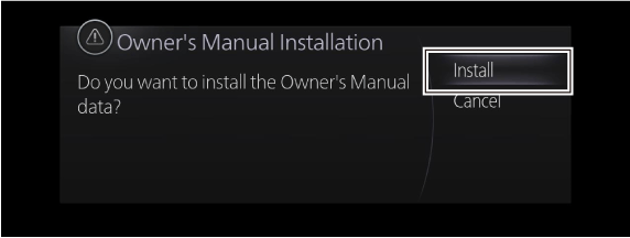
|
8. Select [Install] on the pop up screen.
am3zzw00031658
|
9. Wait for approximately 60 seconds until the installation is completed.
am3zzw00031659
|
10. Installation is completed. Remove the USB memory stick from the USB port.
am3zzw00031660
|
11. Press BACK button and Device Update screen launches.
am3zzw00031656
|
12. Press BACK button again and the diagnostic assist function initial screen launches.
am3zzw00031655
|
13. Select [End Diag Mode] on the diagnostic assist function initial screen and wait for 10 seconds or more.
am3zzw00031662
|
14. The diagnostic assist function ends and the center display initial screen launches.
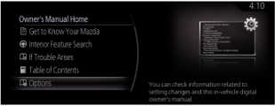
15. Select [Information] > [Owner’s Manual] and confirm OM is displayed on the center display.
16. Select [Options] on the owner’s manual Home screen.
atsuzn00001085
|
17. Select [Version] on the options screen.
atsuzn00001086
|
18. Confirm that the file name for the obtained zip file matches the package number.
atsuzn00001087
|