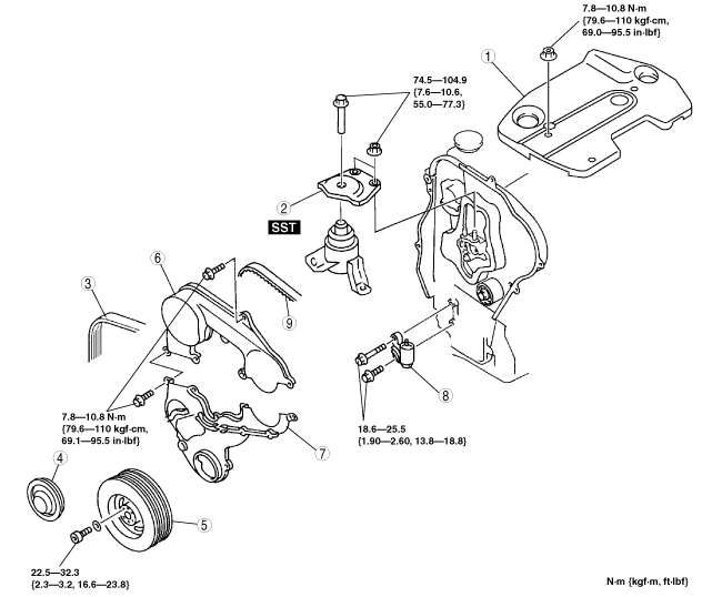
TIMING BELT REMOVAL/INSTALLATION [MZR-CD (RF Turbo)]
TIMING BELT REMOVAL/INSTALLATION [MZR-CD (RF Turbo)]
id0110f1065700
Warning
• Fuel vapor is hazardous. It can very easily ignite, causing serious injury and damage. Always keep sparks and flames away from fuel.
• Fuel line spills and leakage are dangerous. Fuel can ignite and cause serious injures or death and damage. Fuel can also irritate skin and eyes. To prevent this, always complete the “Fuel Line Safety Procedure”. (See BEFORE SERVICE PRECAUTION [MZR-CD (RF Turbo)].)
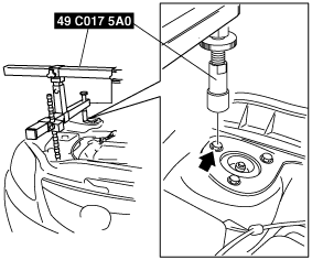
(1) Align the rear support rod hole to the bolt on the shock absorber as shown in the figure.
am6zzw00007444
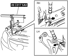
(2) Align the front support rod hole to the bolt of the front side frame as shown in the figure.
am6zzw00007445
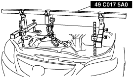
3. Support the engine using the SST.
am6zzw00007446
Note
• The SST (49E 017 5A0) can be used in place of the SST (49C 017 5A0).
Timing Belt, Timing Belt Auto Tensioner Removal Note
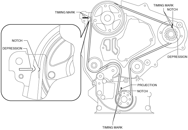
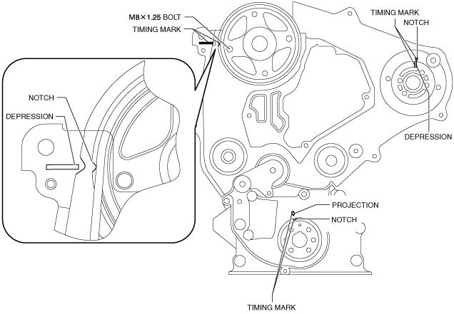
1. Turn the crankshaft clockwise and align the timing marks as shown.
am5ezw00006554
Caution
• Forcefully twisting the belt, turning it inside out, or allowing oil or grease on it will damage the belt and shorten its life.
• After removing the timing belt, do not move the crankshaft and/or camshaft from this position because it can cause the valve and piston to come into contact.
2. Remove the timing belt auto tensioner.
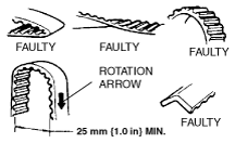
3. Mark the timing belt rotation on the belt for proper reinstallation.
am6zzw00007447
Timing Belt, Timing Belt Auto Tensioner Installation Note
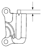
1. Measure the tensioned rod projection length.
• If not as specified, replace the timing belt auto tensioner.
2. Inspect the timing belt auto tensioner for oil leakage.
• If not as specified, replace the timing belt auto tensioner.
Projection (free length)
12.9—14.6 mm {0.508—0.574 in}
am6zzw00007448
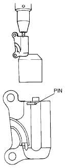
Caution
• Placing the timing belt auto tensioner horizontally can cause oil leakage and damage the timing belt auto tensioner. Place the timing belt auto tensioner vertically when using a vise.
3. Verify the thrust of the timing belt auto tensioner rod in the following order:
• If the timing belt auto tensioner rod is rigid when it is pushed with a force of approximately 235 N {24 kgf, 53 Ibf}, push it down slowly and fix the pin in the hole.
• If there is no resistance on the timing belt auto tensioner rod and it moves slightly when it is pushed with a force of approximately 235 N {24 kgf, 53 Ibf};
(1) Push it down slowly two or three times to the bottom end of the rod.
(2) If the rod protrudes approximately 8.1 mm {0.32 in}, verify that there is resistance on the timing belt auto tensioner rod.
Caution
• To prevent damage to the inside of the timing belt auto tensioner, do not press down the timing belt auto tensioner rod with a force greater than the specified 235 N {24 kgf, 53 lbf}.
Be careful that the rod does not touch the bottom.
• If the timing belt auto tensioner rod projection is restored, push it down slowly and fix the pin in the hole.
― If the resistance is not restored, replace the timing belt auto tensioner.
am6zzw00007449
Caution
• To prevent the bolts from damaging the camshaft pulley, do not fully tighten the fixing bolts. If it contacts the pulley surface, it will damage the pulley.
4. Verify that all timing marks are correctly aligned.
• If not, align all timing marks according to the procedure below.
5. Fix the camshaft pulley to the cylinder head using bolt (M8 x1.25).
am5ezw00006555
Caution
• Turn the crankshaft in the direction which will prevent the TDC and BDC from being passed. Otherwise it can cause the valve and piston to come into contact.
(1) Turn the crankshaft and set it at an angle of 45° or more away from the TDC and BDC.
(2) Align the timing marks of the camshaft pulley.
(3) Align the timing marks of the supply pump pulley.
(4) Turn the crankshaft and align the timing marks of the timing belt pulley.
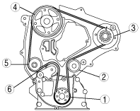
6. Install the timing belt on the pulleys in the order shown below.
(1) Timing belt pulley
(2) Idler
(3) Supply pump pulley
(4) Camshaft pulley
(5) Water pump pulley
(6) Tensioner pulley
am6zzw00007451
7. Remove the camshaft pulley fixing bolt .
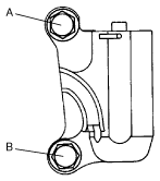
8. Hand tighten the timing belt auto tensioner bolts in the order A to B as indicated in the figure.
9. Tighten the timing belt auto tensioner bolts in the order A to B as indicated in the figure.
Tightening torque
18.6—25.5 N·m {1.90—2.60 kgf·m, 13.8—18.8 ft·lbf}
am6zzw00007452
10. Remove the pin from the timing belt auto tensioner to apply tension to the belt.
11. Turn the crankshaft clockwise twice, and align the timing marks.
12. Verify that all timing marks are correctly aligned.
• If not as specified, repeat from Timing Belt, Timing Belt Auto Tensioner Removal Note.
Crankshaft Pulley Installation Note
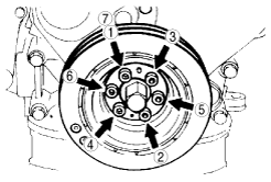
1. Tighten the bolts in the order shown.
Tightening torque
22.5—32.3 N·m {2.3—3.2 kgf·m, 16.6—23.8 ft·lbf}
am6zzw00007453
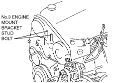
No.3 Engine Joint Bracket Installation Note
1. Tighten the No.3 engine mount bracket stud bolt.
Tightening torque
7.0—13.0 N·m {72—132 kgf·cm, 62—115 in·lbf}
am6zzw00007454
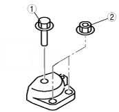
2. Tighten the No.3 engine joint bracket bolt and nut in the order as shown.