GENERATOR INSPECTION [L8, LF, L3, L3 Turbo]
GENERATOR INSPECTION [L8, LF, L3, L3 Turbo]
id0117b1800300
Generator Warning Light
1. Verify that the battery is fully charged.
-
• Charge if necessary.
2. Verify that the drive belt deflection/tension is within the specification. (See DRIVE BELT INSPECTION [L8, LF, L3].) (See DRIVE BELT INSPECTION [L3 Turbo].)
3. Turn the ignition switch on and verify that the generator warning light illuminates.
-
• If not as specified, inspect the generator warning light, and wiring harnesses between the battery and the generator warning light.
4. Verify that the generator warning light goes out after the engine is started.
-
• If not as specified, inspect if any of the following DTCs are displayed: P0112, P0113, P2502, P2503, P2504. (See DTC TABLE [L8, LF, L3].) (See DTC TABLE [L3 Turbo].)
Generator
Voltage
1. Verify that the battery is fully charged.
-
• Charge if necessary.
2. Verify that the drive belt deflection/tension is within the specification. (See DRIVE BELT INSPECTION [L8, LF, L3].) (See DRIVE BELT INSPECTION [L3 Turbo].)
3. Turn off all electrical loads.
4. Turn the ignition switch to start the engine and verify that the generator rotates smoothly without any noise while the engine is running.
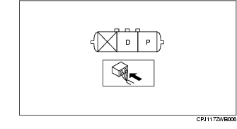
5. Measure the voltage at each terminal using a tester.
-
• If not as specified, repair or replace the generator if necessary.
Generator standard voltage [IG-ON]
-
Terminal B: B+
-
Terminal P: Approx. 1 V
-
Terminal D: Approx. 0 V
Generator standard voltage [Idle, 20 °C {68 °F}]
-
Terminal B: 13-15 V
-
Terminal P: Approx. 3-8 V
-
Terminal D: Turn the electrical loads (headlights, blower motor, rear window defroster) on and verify that the voltage reading increases.
Current
-
Note
-
• Since the charging current decreases rapidly after starting the engine, perform the following procedure quickly, and read the maximum current value.
1. Verify that the battery is fully charged.
-
• Charge if necessary.
2. Verify that the drive belt deflection/tension is within the specification. (See DRIVE BELT INSPECTION [L8, LF, L3].) (See DRIVE BELT INSPECTION [L3 Turbo].)
3. Disconnect the negative battery cable.
4. Connect a tester, which can read 120 A or more, between generator terminal B and the wiring harness.
5. Turn off all electrical loads.
6. Start the engine and increase the engine speed to 2,000-2,500 rpm.
7. Turn the following electrical loads on and verify that the current reading increases.
-
(1) Headlights
-
(2) Blower motor
-
(3) Rear window defroster
-
• If generator terminal B current does not increase, repair or replace the generator if necessary.
-
Note
-
• Current required for generating power varies with the electrical loads applied.
Generator generated current (reference value) [Conditions] Ambient temperature: 20 °C {68 °F}, Voltage: 13.5 V, Engine hot
|
Engine speed (rpm)
|
Terminal B current (Lower limit of current must be more than 0 A.)
|
|
1,000
|
0-80 A
|
|
2,000
|
0-100 A
|
Generator Inner Parts
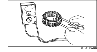
Rotor
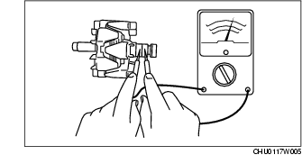
1. Measure the resistance between the slip rings using a tester.
-
• If not within the specification, replace the rotor.
Generator rotor resistance (between slip rings) [20 °C {68 °F}]
-
2.0-2.3 ohm
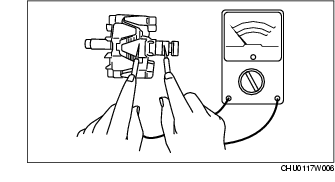
2. Verify that there is no continuity between the slip ring and core using a tester.
-
• If there is continuity, replace the rotor.
3. Inspect the slip ring surface condition.
-
• If the slip ring surface is rough, use a lathe or fine sandpaper to smooth it.
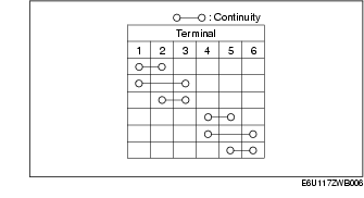
Stator coil
1. Verify that the continuity is as indicated in the table.
-
• If there is any malfunction, replace the stator.
2. Verify that there is no continuity between the stator coil leads and core using a tester.
-
• If there is continuity, replace the stator coil.
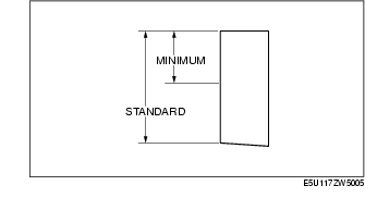
Brush
1. Inspect brushes for wear.
-
• If any brush is worn almost to or beyond the limit, replace all of the brushes.
Generator brush length
-
Standard: 22.5 mm {0.89 in}
-
Minimum: 5.0 mm {0.20 in}
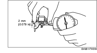
Brush spring
1. Measure the force of the brush spring using a spring pressure gauge.
2. Read the spring pressure gauge at the brush tip projection of 2 mm {0.079 in}.
-
• Replace the brush spring if necessary.
Generator brush spring force
-
Standard: 4.1-5.3 N {0.42-0.54 kgf, 0.92-1.19 lbf}
-
Minimum: 1.7 N {0.17 kgf, 0.38 lbf}
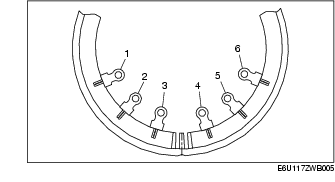
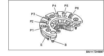
Rectifier (Using an analog circuit tester)
1. Inspect for continuity of the diodes using an analog circuit tester.
-
• If not as specified, replace the rectifier.
Specification
|
Negative
|
Positive
|
Continuity
|
|
E
|
P1, P2, P3, P4, P5, P6
|
Yes
|
|
B
|
No
|
|
P1, P2, P3, P4, P5, P6
|
E
|
No
|
|
B
|
Yes
|
Rectifier (Using a digital circuit tester)
1. Inspect for continuity of the diodes using a digital circuit tester.
-
• If not as specified, replace the rectifier.
Specification
|
Negative
|
Positive
|
Continuity
|
|
E
|
P1, P2, P3, P4, P5, P6
|
No
|
|
B
|
Yes
|
|
P1, P2, P3, P4, P5, P6
|
E
|
Yes
|
|
B
|
No
|
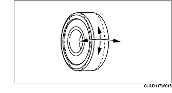
Bearing
1. Inspect for abnormal noise, looseness, and sticking.
-
• Replace the bearing if necessary.