STARTER INSPECTION [L8, LF, L3, L3 Turbo]
STARTER INSPECTION [L8, LF, L3, L3 Turbo]
id0119a3800300
On-vehicle Inspection
1. Verify that the battery is fully charged.
2. The starter is normal if it rotates smoothly and without any noise when the engine is cranked.
-
• If the starter does not operate, inspect the following:
-
- Remove the starter, and inspect the starter unit.
-
- Inspect the related wiring harnesses, the ignition switch, and the transaxle range switch (ATX).
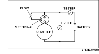
No-load test
1. Verify that the battery is fully charged.
2. Connect the starter, battery, and a tester as shown in the figure.
3. Operate the starter and verify that it rotates smoothly.
-
• If the starter does not rotate smoothly, inspect the starter unit.
4. Measure the voltage and current while the starter is operating.
-
• If not within the specification, replace the starter.
Starter no load test voltage
-
11 V
Starter no load test current
-
90 A or less
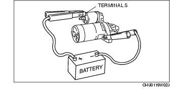
Magnetic Switch Operation Inspection
Pull-out test
-
Note
-
• Depending on the battery charge condition, the starter motor pinion may rotate while in an extended state. This is due to current flowing to the starter motor through the pull-in coil to turn the starter motor, and does not indicate an abnormality.
1. Verify that the starter motor pinion is extended while battery positive voltage is connected to terminal S and the starter body is grounded.
-
• If the starter motor pinion is not extended, repair or replace the starter.
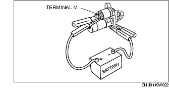
Return test
1. Disconnect the motor wire from terminal M.
2. Connect battery positive voltage to terminal M and ground the starter body.
3. Pull out the drive pinion with a screwdriver. Verify that it returns to its original position when released.
-
• If it does not return, repair or replace the starter.
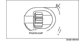
Pinion Gap Inspection
1. Pull out the drive pinion with the battery positive voltage connected to terminal S and the starter body grounded.
-
Caution
-
• Applying power for more than 10 s can damage the starter. Do not apply power for more than 10 s.
2. Measure the pinion gap while the drive pinion is extended.
-
• If not as specified, adjust with an adjustment washer (between drive housing front cover and magnetic switch).
Starter pinion gap
-
0.5-2.0 mm {0.02-0.07 in}
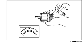
Starter Inner Parts Inspection
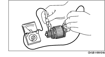
Armature
1. Verify that there is no continuity between the commutator and the core at each segment using a tester.
-
• If there is continuity, replace the armature.
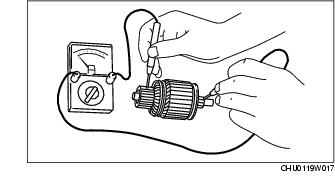
2. Verify that there is no continuity between the commutator and the shaft using a tester.
-
• If there is continuity, replace the armature.
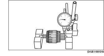
3. Place the armature on V-blocks, and measure the runout using a dial indicator.
Starter armature runout
-
0.05 mm {0.002 in} max.
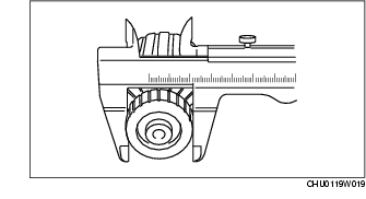
4. Measure the commutator diameter.
-
• If not within the minimum specification, replace the armature.
Starter commutator diameter
-
Standard: 29.4 mm {1.16 in}
-
Minimum: 28.8 mm {1.13 in}
5. Measure the segment groove depth of the commutator.
-
• If not within the minimum specification, undercut the grooves to the standard depth.
Segment groove depth of starter commutator
-
Standard: 0.4-0.6 mm {0.016-0.023 in}
-
Minimum: 0.2 mm {0.008 in}
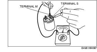
Magnetic switch
1. Inspect for continuity between terminals S and M using a tester.
-
• If there is no continuity, replace the magnetic switch.
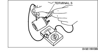
2. Inspect for continuity between terminal S and the body using a tester.
-
• If there is no continuity, replace the magnetic switch.
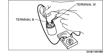
3. Verify that there is no continuity between terminals M and B using a tester.
-
• If there is continuity, replace the magnetic switch.
Brush and brush holder
1. Verify that there is no continuity between each insulated brush and plate using a tester.
-
• If there is continuity, replace the brush holder.
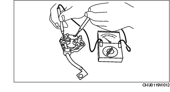
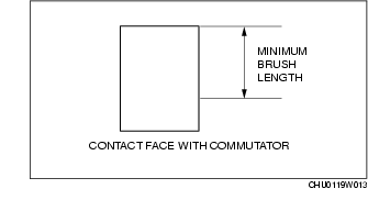
2. Measure the brush length.
-
• If any brush is worn almost to or beyond the minimum specification, replace all of the brushes.
Starter brush length
-
Standard: 12.3 mm {0.48 in}
-
Minimum: 7.0 mm {0.28 in}
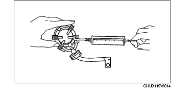
3. Measure the brush spring force using a spring balance.
-
• If not within the minimum specification, replace the brush and brush holder component.
Starter brush spring force
-
Standard: 18.3-24.9 N {1.87-2.53 kgf, 4.12-5.59 lbf}
-
Minimum: 5.9 N {0.6 kgf, 1.3 lbf}