BOOST SENSOR INSPECTION [MZR-CD (RF Turbo)]
BOOST SENSOR INSPECTION [MZR-CD (RF Turbo)]
id0140f1809700
-
Note
-
• Perform the following test only when directed.
Visual Inspection
1. Inspect the boost sensor for damage and cracks.
-
• If not as specified, replace the boost sensor.
2. Inspect vacuum hose for improper routing, kinks or leakage.
-
• If there is any malfunction, repair or replace suspected hose.
Voltage Inspection
1. Turn the engine switch to ON.
2. Monitor the MAP PID using the WDS or equivalent.
-
• If not as specified, perform the "Circuit Open/Short Inspection".
-
- If there is no open/short circuit, replace the boost sensor. (See INTAKE-AIR SYSTEM REMOVAL/INSTALLATION [MZR-CD (RF Turbo)])
MAP PID
-
0.6-1.0 V
3. Start the engine and warm up the engine completely.
4. Monitor the MAP PID using the WDS or equivalent at idle.
-
• If not as specified, perform the "Circuit Open/Short Inspection".
-
- If there is no open/short circuit, replace the boost sensor. (See INTAKE-AIR SYSTEM REMOVAL/INSTALLATION [MZR-CD (RF Turbo)])
MAP PID
-
0.6-1.0 V
Circuit Open/Short Inspection
1. Disconnect the PCM connector. (See PCM REMOVAL/INSTALLATION [MZR-CD (RF Turbo)])
2. Disconnect the boost sensor connector.
3. Inspect for open/short circuit in the following wiring harnesses.
-
• If there is open/short circuit, repair or replace wiring harnesses.
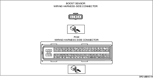
Open circuit
-
• Boost sensor terminal A and PCM terminal 71
-
• Boost sensor terminal B and PCM terminal 52
-
• Boost sensor terminal C and PCM terminal 59
Short circuit
-
• Boost sensor terminal A and power supply
-
• Boost sensor terminal B and power supply
-
• Boost sensor terminal B and body ground
-
• Boost sensor terminal C and power supply
-
• Boost sensor terminal C and body ground