Diagnostic procedure
|
STEP
|
INSPECTION
|
ACTION
|
|
|---|---|---|---|
|
1
|
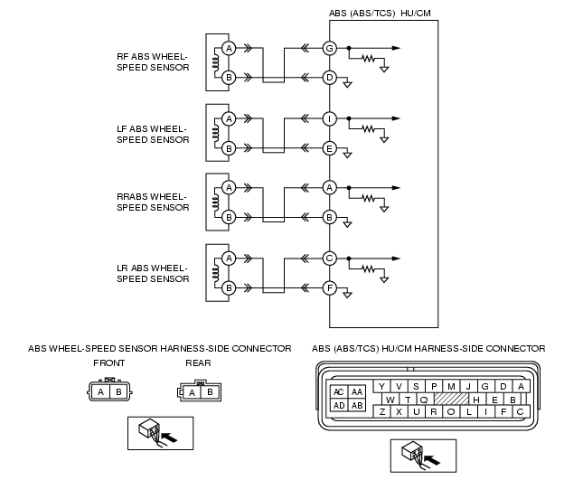
INSPECT ABS WHEEL-SPEED SENSOR CIRCUIT FOR OPEN CIRCUIT
• Turn the ignition switch off.
• Disconnect ABS (ABS/TCS) HU/CM connector.
• Measure resistance between suspected sensor terminals of ABS (ABS/TCS) HU/CM connector (harness-side).
• Is resistance within 1.3-1.7 kilohm?
|
Yes
|
Go to the next step.
|
|
No
|
Go to Step 3.
|
||
|
2
|
INSPECT ABS WHEEL-SPEED SENSOR CIRCUIT FOR SHORT TO GROUND
• Turn the ignition switch off.
• Inspect continuity between suspected sensor terminal (s) of ABS (ABS/TCS) HU/CM connector (harness-side) and ground (s).
• Is there continuity?
|
Yes
|
Repair or replace harness for short to ground circuit between ABS (ABS/TCS) HU/CM and ABS wheel-speed sensor (s), then go to Step 5.
|
|
No
|
Go to Step 5.
|
||
|
3
|
INSPECT ABS WHEEL-SPEED SENSOR
• Turn the ignition switch off.
• Disconnect suspected sensor connector (s) and inspect resistance between sensor terminals (part side).
• Is resistance within 1.3-1.7 kilohm?
|
Yes
|
Go to the next step.
|
|
No
|
Replace ABS wheel-speed sensor, then go to Step 5.
|
||
|
4
|
INSPECT ABS (ABS/TCS) HU/CM TO ABS WHEEL-SPEED SENSOR CIRCUIT FOR OPEN CIRCUIT
• Inspect continuity between suspected sensor terminal (s) of ABS (ABS/TCS) HU/CM connector (harness-side) and ABS wheel-speed sensor connector. (vehicle harness-side)
• Is there continuity?
|
Yes
|
Repair or replace poor connections of ABS (ABS/TCS) HU/CM connector and/or ABS wheel-speed sensor connector (s), then go to the next step.
|
|
No
|
Repair or replace harness for open circuits between ABS (ABS/TCS) HU/CM and ABS wheel-speed sensor (s), then go to the next step.
|
||
|
5
|
VERIFY TROUBLESHOOTING COMPLETED
• Make sure to reconnect all disconnected connectors.
• Clear the DTC from the memory
(See Clearing DTCs Procedures.)
• Is same DTC present?
|
Yes
|
Replace ABS (ABS/TCS) HU/CM, then go to the next step.
|
|
No
|
Go to the next step.
|
||
|
6
|
VERIFY AFTER REPAIR PROCEDURE
• Is there any other DTC present?
|
Yes
|
Go to the applicable DTC inspection.
(See DTC Table.)
|
|
No
|
Troubleshooting completed.
|
||