Diagnostic procedure
|
STEP
|
INSPECTION
|
ACTION
|
|
|---|---|---|---|
|
1
|
VERIFY OTHER DTC HAS BEEN RECORDED
• Have DTCs related to solenoid valve, pump motor, or pump motor relay been stored?
|
Yes
|
Go to the applicable DTC inspection.
|
|
No
|
Go to the next step.
|
||
|
2
|
VERIFY IF CURRENT CONCERNED INPUT SIGNAL STATUS IS INTERMITTENT OR CONSTANT
• Turn the ignition switch off.
• Connect WDS or equivalent to DLC-2.
• Start engine and drive vehicle.
• Access LF_WSPD, LR_WSPD, RF_WSPD and RR_WSPD using the WDS or equivalent
• Do vehicle speeds correspond approximately to the four PIDs above?
|
Yes
|
Go to Step 8.
|
|
No
|
If there is a difference in speed of four wheels: Go to the next step.
If any wheel speed is 0 km/h {0 mph}: Go to Step 4.
|
||
|
3
|
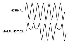
INSPECT ABS WHEEL-SPEED SENSOR OUTPUT PULSE
• Start engine and drive vehicle.
• Inspect output voltage pattern using an oscilloscope.
|
Yes
|
Go to Step 9.
|
|
|
No
|
Go to Step 6.
|
|
|
• Is output voltage pattern okay?
|
|||
|
4
|
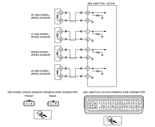
INSPECT ABS WHEEL-SPEED SENSOR CIRCUIT FOR SHORT TO GROUND
• Turn the ignition switch off.
• Disconnect ABS (ABS/TCS) HU/CM and ABS wheel-speed sensor connectors.
• Inspect continuity between suspected sensor terminal (s) of ABS (ABS/TCS) HU/CM connector (harness side) and ground (s).
• Is there continuity?
|
Yes
|
Repair or replace harness for short to ground circuit between ABS (ABS/TCS) HU/CM and ABS wheel-speed sensor, then go to Step 9.
|
|
No
|
Go to the next step.
|
||
|
5
|
INSPECT ABS WHEEL-SPEED SENSOR
• Turn the ignition switch off.
• Disconnect suspected ABS wheel-speed sensor connector (s) and inspect resistance between ABS wheel-speed sensor terminal (s) (part side).
• Is resistance within 1.3-1.7 kilohm?
|
Yes
|
Go to the next step.
|
|
No
|
Replace ABS wheel-speed sensor (s), then go to Step 9.
|
||
|
6
|
INSPECT SENSOR ROTOR CLEARANCE
• Jack-up vehicle and support it with safety stands.
• Remove suspected wheel (s).
• Inspect clearance between ABS wheel-speed sensor and sensor rotor.
• Is clearance within 0.3-1.1 mm {0.012-0.043 in}?
|
Yes
|
Go to the next step.
|
|
No
|
Replace ABS wheel-speed sensor (s), then go to Step 9.
|
||
|
7
|
INSPECT SENSOR ROTOR FOR DAMAGE
• Jack-up vehicle and support it with safety stands.
• Remove suspected wheel (s).
• Visually inspect sensor rotor for missing, deformed and obstructed teeth.
Number of teeth: 44
• Is sensor rotor okay?
|
Yes
|
Go to the next step.
|
|
No
|
Replace sensor rotor, then go to Step 9.
|
||
|
8
|
INSPECT ABS (ABS/TCS) HU/CM OPERATION
• Perform ABS (ABS/TCS) HU/CM system inspection.
• Is it normal?
|
Yes
|
Go to the next step.
|
|
No
|
Replace ABS (ABS/TCS) HU/CM, then go to the next step.
|
||
|
9
|
VERIFY TROUBLESHOOTING COMPLETED
• Make sure to reconnect all disconnected connectors.
• Clear the DTC from the memory
(See Clearing DTCs Procedures)
• Start engine and drive vehicle at 10 km/h {6.2 mph} or above.
• Gradually slow down vehicle and stop.
• Is same DTC present?
|
Yes
|
Replace ABS (ABS/TCS) HU/CM, then go to the next step.
|
|
No
|
Go to the next step.
|
||
|
10
|
VERIFY AFTER REPAIR PROCEDURE
• Is there any other DTC present?
|
Yes
|
Go to the applicable DTC inspection.
(See DTC Table.)
|
|
No
|
Troubleshooting completed.
|
||