Diagnostic procedure
|
STEP
|
INSPECTION
|
ACTION
|
|
|---|---|---|---|
|
1
|
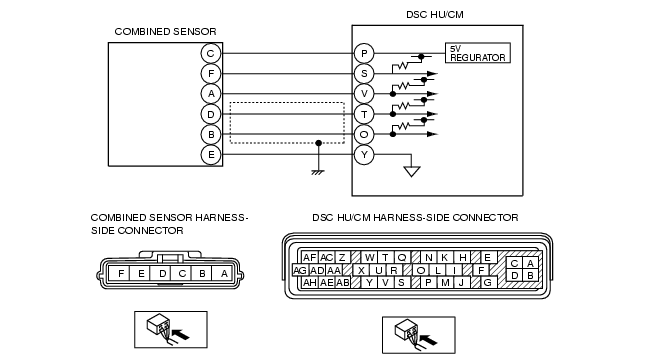
INSPECT COMBINED SENSOR POWER SUPPLY CIRCUIT FOR OPEN CIRCUIT
• Turn ignition key to ON (engine OFF).
• Measure voltage between combined sensor terminal C (harness side) and ground.
• Is voltage 4.5-5.5 V?
|
Yes
|
Go to next step.
|
|
No
|
Repair or replace harness for open circuit between combined sensor terminal C and ignition switch, then go to Step 8.
|
||
|
2
|
INSPECT COMBINED SENSOR GROUND CIRCUIT FOR OPEN CIRCUIT
• Turn ignition key to OFF.
• Disconnect DSC HU/CM and combined sensor connectors.
• Inspect continuity between DSC HU/CM terminal Y (harness side) and combined sensor terminal E (harness side).
• Is there continuity?
|
Yes
|
Go to next step.
|
|
No
|
Repair or replace harness for open circuit between DSC HU/CM terminal Y and combined sensor terminal E, then go to Step 8.
|
||
|
3
|
INSPECT FORWARD-G SENSOR PART SIGNAL CIRCUIT FOR OPEN CIRCUIT
• Inspect continuity between DSC HU/CM terminal V (harness side) and combined sensor terminal A (harness side).
• Is there continuity?
|
Yes
|
Go to next step.
|
|
No
|
Repair or replace harness for open circuit between DSC HU/CM terminal V and combined sensor terminal A, then go to Step 8.
|
||
|
4
|
INSPECT FORWARD-G SENSOR PART SIGNAL CIRCUIT FOR SHORT TO GROUND
• Turn ignition key to OFF.
• Inspect continuity between DSC HU/CM terminal V (harness side) and ground.
• Is there continuity?
|
Yes
|
Repair or replace harness for short to ground circuit between DSC HU/CM terminal V and combined sensor terminal A, then go to Step 8.
|
|
No
|
Go to next step.
|
||
|
5
|
INSPECT DIAGNOSIS SIGNAL CIRCUIT FOR SHORT FOR OPEN CIRCUIT
• Turn ignition key to OFF.
• Inspect continuity between DSC HU/CM terminal S (harness side) and combined sensor terminal F.
• Is there continuity?
|
Yes
|
Repair or replace harness for open circuit between DSC HU/CM terminal S and combined sensor terminal F, then go to Step 8.
|
|
No
|
Go to next step.
|
||
|
6
|
INSPECT DIAGNOSIS SIGNAL CIRCUIT FOR SHORT TO GROUND
• Turn ignition key to OFF.
• Inspect continuity between DSC HU/CM terminal S (harness side) and ground.
• Is there continuity?
|
Yes
|
Repair or replace harness for short to ground circuit between DSC HU/CM terminal S and combined sensor terminal F, then go to Step 8.
|
|
No
|
Go to next step.
|
||
|
7
|
INSPECT COMBINED SENSOR
• Inspect combined sensor.
• Is it normal?
|
Yes
|
Go to next step.
|
|
No
|
Replace combined sensor, then go to next step.
|
||
|
8
|
VERIFY TROUBLESHOOTING COMPLETED
• Clear DTC from memory.
(See Clearing DTCs Procedures.)
• Is same DTC present?
|
Yes
|
Replace DSC HU/CM, then go to next step.
|
|
No
|
Go to next step.
|
||
|
9
|
VERIFY THAT NO OTHER DTCS ARE PRESENT
• Are any other DTCs output?
|
Yes
|
Go to the applicable DTC inspection.
(See DTC Table.)
|
|
No
|
DTC troubleshooting completed.
|
||