1. Disconnect the negative battery cable.
2. Remove the air cleaner component. (See INTAKE AIR SYSTEM REMOVAL/INSTALLATION [L8, LF, L3].)
3. Disconnect the TR switch connector.
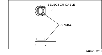
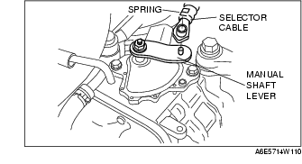
4. Remove the spring and disconnect the selector cable.
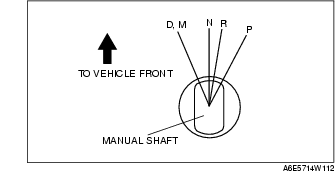
5. Rotate the manual shaft to the N position.
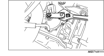
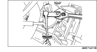
6. Set the adjustable wrench as shown to hold the manual shaft lever.
7. Remove the manual shaft nut and washer.
8. Remove the manual shaft lever.
9. Remove the TR switch.
10. Rotate the manual shaft to the right fully, them return 2 notches to set the N position.
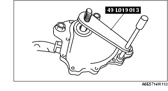
11. Using the SST and by turning the TR switch, adjust the positions of the manual shaft and the TR switch neutral hole.
12. Tighten the TR switch mounting bolts.
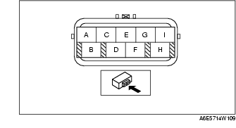
Tightening torque13. Inspect for continuity at the TR switch between terminals C and D.
14. Remove the SST.
15. Install the manual shaft lever and washer.
16. Set the adjustable wrench as shown to hold the manual shaft lever.
17. Tighten the manual shaft nut using a torque wrench.
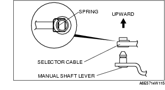
Tightening torque18. Install the spring as shown in the figure.
19. Verify that the selector lever range position and TR switch are aligned, then connect the selector cable.
20. Inspect for continuity at the TR switch. (See Inspection of Continuity.)
21. Connect the TR switch connector.
22. Install the air cleaner component. (See INTAKE AIR SYSTEM REMOVAL/INSTALLATION [L8, LF, L3].)
23. Connect the negative battery cable.
24. Inspect operation of the TR switch. (See Inspection of Operation.)