 |
am6zzw00004795
CLIMATE CONTROL UNIT INSPECTION
id074000802200
Full-auto Air Conditioner
1. Connect the all center panel connectors.
2. Turn the ignition switch to ON position.
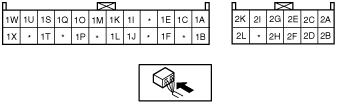
3. Measure the voltage at each climate control unit terminal and refer to the terminal voltage list.
Terminal Voltage List (Reference)
am6zzw00004795
|
|
Terminal |
Signal |
Connected to |
Test condition |
Voltage (V) |
Action |
|---|---|---|---|---|---|
|
1A
|
Blower motor feedback signal
|
• Blower motor
• Power MOS FET
|
Fan switch is OFF
|
12
|
1. Inspect for continuity or short circuit (Climate control unit—blower motor: 1A—A) (Climate control unit—power MOS FET: 1A—B, 1C—E) (Blower motor—blower relay: B—C) (Blower relay—fuse: D—BLOWER 40 A fuse)
2. Inspect for continuity (Power MOS FET—ground: A—GND) (Blower relay—ground: A—GND)
3. Inspect power MOS FET
4. Inspect blower motor
5. Inspect blower relay
6. Inspect BLOWER 40 A fuse
7. Replace power MOS FET
|
|
Fan switch is at manual LO
|
7.8
|
||||
|
Fan switch is at manual HI
|
0.2
|
||||
|
1B
|
+5 V
|
• Air mix actuator
• Airflow mode actuator
• Solar radiation sensor
|
Ignition switch at ON position
|
5.0
|
• Inspect for short circuit (Climate control unit— air mix actuator, airflow mode actuator, solar radiation sensor: 1B—A (L.H.D.) or B (R.H.D.), B, A)
• Inspect air mix actuator
• Inspect airflow mode actuator
• Inspect solar radiation sensor
• Inspect terminal voltage of climate control unit connector (2H, 2L)
|
|
Ignition switch at LOCK position
|
Below 1.0
|
• Replace climate control unit
|
|||
|
1C
|
Blower motor control signal
|
Power MOS FET
|
Fan switch is OFF
|
Below 1.0
|
• Inspect terminal voltage of climate control unit (1A)
|
|
Fan switch is at manual LO
|
4.1
|
||||
|
Fan switch is at manual HI
|
7.9
|
||||
|
1D
|
—
|
—
|
—
|
—
|
—
|
|
1E
|
Rear window defroster SW signal
|
Rear window defroster relay
|
Rear window defroster switch is off
|
12
|
• Inspect for continuity or short circuit (Climate control unit—rear window defroster relay: 1E—E)
• Inspect rear window defroster relay
|
|
Rear window defroster switch is on
|
Below 1.0
|
• Inspect terminal voltage of climate control unit (2H, 2L)
• Inspect center panel
|
|||
|
1F
|
On-board diagnostic signal
|
A/C check connector
|
Terminal A of A/C check connector is shorted.
|
Below 1.0
|
• Inspect for continuity (Climate control unit—A/C check connector: 1F—A)
|
|
Other
|
5.4
|
• Inspect short circuit (Climate control unit—A/C check connector: 1F—A)
• Inspect terminal voltage of climate control unit (2H, 2L)
|
|||
|
1G
|
—
|
—
|
—
|
—
|
—
|
|
1H
|
—
|
—
|
—
|
—
|
—
|
|
1I
|
GND
|
• Cabin temperature sensor
• Evaporator temperature sensor
• Ambient temperature sensor
• Water temperature sensor
• Air mix actuator
• Airflow mode actuator
|
Under any condition
|
Below 1.0
|
• Inspect terminal voltage of climate control unit (2L)
|
|
1J
|
Water heater select (MZR-CD (RF Turbo))
|
Ground
|
Under any condition
|
Below 1.0
|
• Inspect for continuity (Climate control unit—ground: 1J—GND)
• Inspect center panel
|
|
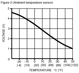
1K
|
Ambient temperature sensor input
|
Ambient temperature sensor
|
Depends on temperature surrounding sensor
|
See Figure 2
|
• Inspect for continuity (Climate control unit— ambient temperature sensor: 1K—B, 1I—A)
• Inspect for short circuit (Climate control unit— ambient temperature sensor: 1K—B)
• Inspect ambient temperature sensor
• Inspect terminal voltage of climate control unit (2H, 2L)
|
|
1L
|
MZR-CD (RF Turbo) select
|
Ground
|
Under any condition
|
Below 1.0
|
• Inspect for continuity (Climate control unit—ground: 1L—GND)
• Inspect center panel
|
|
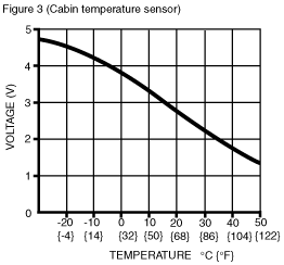
1M
|
Cabin temperature sensor input
|
Cabin temperature sensor
|
Depends on temperature surrounding sensor
|
See Figure 3
|
• Inspect for continuity (Climate control unit— cabin temperature sensor: 1M—B, 1I—A)
• Inspect for short circuit (Climate control unit— cabin temperature sensor: 1M—B)
• Inspect cabin temperature sensor
• Inspect terminal voltage of climate control unit (2H, 2L)
|
|
1N
|
—
|
—
|
—
|
—
|
—
|
|
1O
|
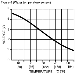
Water temperature sensor input
|
Water temperature sensor
|
Depends on temperature surrounding sensor
|
See Figure 4
|
• Inspect for continuity (Climate control unit—water temperature sensor: 1O—A, 1I—B)
• Inspect for short circuit (Climate control unit—water temperature sensor: 1O—A)
• Inspect water temperature sensor
• Inspect terminal voltage of climate control unit (2H, 2L)
|
|
1P
|
A/C
|
Refrigerant pressure switch
|
Fan switch at OFF
|
12
|
• Inspect for continuity or short circuit (Climate control unit—refrigerant pressure switch: 1P—A (Dual-pressure type), 1P—C (Triple-pressure type)) (Refrigerant pressure switch—PCM: B—1AC (except MZR-CD (RF Turbo)), 84 (MZR-CD (RF Turbo)))
• Inspect refrigerant pressure switch
• Inspect PCM terminal voltage (1AC (except MZR-CD (RF Turbo)), 84 (MZR-CD (RF Turbo)))
|
|
Fan switch at 1st position, A/C switch ON
|
Below 1.0
|
• Inspect terminal voltage of climate control unit (2H, 2L)
|
|||
|
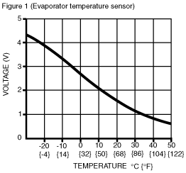
1Q
|
Evaporator temperature sensor input signal
|
Evaporator temperature sensor
|
Depends on temperature surrounding sensor
|
See Figure 1
|
• Inspect for continuity (Climate control unit— evaporator temperature sensor: 1Q—B, 1I—A)
• Inspect for short circuit (Climate control unit— evaporator temperature sensor: 1Q—B)
• Inspect evaporator temperature sensor
• Inspect terminal voltage of climate control unit (2H, 2L)
|
|
1R
|
—
|
—
|
—
|
—
|
—
|
|
1S
|
Solar radiation sensor input
|
Solar radiation sensor
|
Incandescent light (60W) shining on solar radiation sensor from distance of approx. 100mm {3.9 in}
|
4.0
|
• Inspect for continuity or short circuit (Climate control unit—solar radiation sensor: 1S—B, 1B—A)
• Inspect terminal voltage of climate control unit (1B)
• Inspect solar radiation sensor
|
|
Light to solar radiation sensor block
|
Below 1.0
|
||||
|
1T
|
GND
|
Ground
|
Under any condition
|
Below 1.0
|
• Inspect for continuity (Climate control unit—ground: 1T—GND)
• Inspect center panel
|
|
1U
|
Potentiometer signal
|
Air mix actuator
|
Set temperature at MAX COLD
|
0.6
|
• Inspect for continuity or short circuit (Climate control unit—air mix actuator: 1U—C)
• Inspect air mix actuator
• Inspect terminal voltage of climate control unit (1B)
|
|
Set temperature at MAX HOT
|
4.3
|
||||
|
1V
|
—
|
—
|
—
|
—
|
—
|
|
1W
|
Potentiometer signal
|
Airflow mode actuator
|
VENT mode
|
4.3
|
• Inspect for continuity or short circuit (Climate control unit—airflow mode actuator: 1W—C)
• Inspect airflow mode actuator
• Inspect terminal voltage of climate control unit (1B)
|
|
BI-LEVEL mode
|
3.3
|
||||
|
HEAT mode
|
2.3
|
||||
|
HEAT/DEF mode
|
1.5
|
||||
|
DEFROSTER mode
|
0.6
|
||||
|
1X
|
Hazard warning SW signal
|
Hazard warning switch
|
Hazard warning switch is off
|
12
|
• Inspect for continuity or short circuit (Climate control unit—flasher unit: 1X—H)
• Inspect flasher unit
|
|
Hazard warning switch is on
|
Below 1.0
|
• Inspect terminal voltage of climate control unit (1T)
• Inspect center panel
|
|||
|
2A
|
Panel light control signal
|
Panel light control switch
|
Headlight switch ON and panel light control switch at max. illumination
|
0.2
|
• Inspect for continuity (Climate control unit— panel light control switch: 2A—C) (Panel light control switch—ground: C—GND)
• Inspect panel light control switch
|
|
Headlight switch ON and panel light control switch at min. illumination
|
10.2
|
• Inspect for short circuit (Climate control unit— panel light control switch: 2A—C)
|
|||
|
2B
|
TNS signal
|
TNS relay
|
Headlight switch OFF
|
Below 1.0
|
• Inspect for short circuit (Climate control unit—TNS relay: 2B—D)
• Inspect TNS relay
• Inspect headlight switch
|
|
Headlight switch ON
|
12
|
• Inspect for continuity or short circuit (Climate control unit—TNS relay: 2B—D)
• Inspect TNS relay
• Inspect headlight switch
|
|||
|
2C
|
Motor drive signal
|
Air mix actuator
|
Moving to COLD
|
12
|
• Inspect for continuity or short circuit (Climate control unit—air mix actuator: 2D—F (L.H.D.) or D (R.H.D.), 2C—D (L.H.D.) or F (R.H.D.))
• Inspect air mix actuator
|
|
Moving to HOT
|
Below 1.0
|
||||
|
2D
|
Motor drive signal
|
Air mix actuator
|
Moving to HOT
|
12
|
• Inspect for continuity or short circuit (Climate control unit—air mix actuator: 2C—D (L.H.D.) or F (R.H.D.), 2D—F (L.H.D.) or D (R.H.D.))
• Inspect air mix actuator
|
|
Moving to COLD
|
Below 1.0
|
||||
|
2E
|
Motor drive signal
|
Airflow mode actuator
|
Moving to DEFROSTER
|
12
|
• Inspect for continuity or short circuit (Climate control unit—airflow mode actuator: 2E—F, 2G—D)
• Inspect airflow mode actuator
|
|
Moving to VENT
|
Below 1.0
|
||||
|
2F
|
Backup power supply
|
ROOM 15 A fuse
|
Under any condition
|
B+
|
• Inspect for continuity or short circuit (Climate control unit—fuse: 2F— ROOM 15 A fuse)
• Inspect ROOM 15 A fuse
|
|
2G
|
Motor drive signal
|
Airflow mode actuator
|
Moving to VENT
|
12
|
• Inspect for continuity or short circuit (Climate control unit—airflow mode actuator: 2G—D, 2E—F)
• Inspect airflow mode actuator
|
|
Moving to DEFROSTER
|
Below 1.0
|
||||
|
2H
|
IG2
|
A/C 10 A fuse
|
Ignition switch at ON position
|
B+
|
• Inspect for continuity or short circuit (Climate control unit—fuse: 2H—A/C 10 A fuse)
• Inspect A/C 10 A fuse
|
|
Ignition switch at LOCK position
|
Below 1.0
|
• Inspect for short circuit (Climate control unit—fuse: 2H—A/C 10 A fuse)
|
|||
|
2I
|
Motor drive signal
|
Air intake actuator
|
Moving to RECIRCULATE
|
12
|
• Inspect for continuity or short circuit (Climate control unit—air intake actuator: 2I—F, 2K—D)
• Inspect air intake actuator
|
|
Moving to FRESH
|
Below 1.0
|
||||
|
2J
|
—
|
—
|
—
|
—
|
—
|
|
2K
|
Motor drive signal
|
Air intake actuator
|
Moving to FRESH
|
12
|
• Inspect for continuity or short circuit (Climate control unit—air intake actuator: 2K—D, 2I—F)
• Inspect air intake actuator
|
|
Moving to RECIRCULATE
|
Below 1.0
|
||||
|
2L
|
GND
|
Ground
|
Under any condition
|
Below 1.0
|
• Inspect for continuity (Climate control unit—ground: 2L—GND)
|
 |
 |
 |
 |