PROCEDURES FOR DETERMINING THE LOCATION OF A MALFUNCTION
PROCEDURES FOR DETERMINING THE LOCATION OF A MALFUNCTION
id0902e6830500
System Wiring Diagram
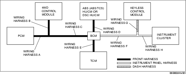
PCM
1. Check the display of DTC U0101, U0121 and/or U0155, using the SST (WDS or equivalent). (See DTC TABLE [MULTIPLEX COMMUNICATION SYSTEM].)
2. Referring to the following table, determine the malfunctioning part of the CAN system.
X: Normal
-: Communication error
|
Module
|
Communication status
|
Malfunction location
|
|
TCM
|
ABS (ABS/TCS) HU/CM
DSC HU/CM
|
Instrument cluster
|
|
PCM
|
-
|
-
|
-
|
• Wiring harness A
• Wiring harness C
• PCM
|
|
-
|
X
|
X
|
• Wiring harness E
• BCM
• TCM
|
|
X
|
-
|
X
|
• Wiring harness D
• BCM
• ABS (ABS/TCS) HU/CM
• DSC HU/CM
|
|
X
|
X
|
-
|
• Wiring harness F
• Wiring harness H
• BCM
• Instrument cluster
|
TCM
1. Check the display of DTC U0100 using the SST (WDS or equivalent). (See DTC TABLE [MULTIPLEX COMMUNICATION SYSTEM].)
2. Access and monitor the "TCM_MSG" of ABS/TCS HU/CM, DSC HU/CM and instrument cluster PID using the SST (WDS or equivalent).
3. Referring to the PID/DATA MONITOR, confirm the display status of the PID. (See PID/DATA MONITOR TABLE [MULTIPLEX COMMUNICATION SYSTEM].)
4. Referring to the following table, determine the malfunctioning part of the CAN system.
X: Normal
-: Communication error
|
Module
|
Communication status
|
Malfunction location
|
|
PCM
|
ABS (ABS/TCS) HU/CM
DSC HU/CM
|
Instrument cluster
|
|
TCM
|
-
|
-
|
-
|
• Wiring harness E
• BCM
• TCM
|
|
-
|
X
|
X
|
• Wiring harness A
• Wiring harness C
• BCM
• PCM
|
|
X
|
-
|
X
|
• Wiring harness D
• ABS (ABS/TCS) HU/CM
• DSC HU/CM
|
|
X
|
X
|
-
|
• Wiring harness F
• Wiring harness H
• Instrument cluster
|
ABS (ABS/TCS) HU/CM or DSC HU/CM
1. Check the display of DTC U0100, U0101, U0114, U0155 and/or U2511, using the SST (WDS or equivalent). (See DTC TABLE [MULTIPLEX COMMUNICATION SYSTEM].)
2. Access and monitor the "PCM_MSG", "TCM_MSG", "IC_MSG" and "AWD_MSG" of PID using the SST (WDS or equivalent).
3. Referring to the PID/DATA MONITOR, confirm the display status of the PID. (See PID/DATA MONITOR TABLE [MULTIPLEX COMMUNICATION SYSTEM].)
4. Referring to the following table, determine the malfunctioning part of the CAN system.
X: Normal
-: Communication error
|
Module
|
Communication status
|
Malfunction location
|
|
PCM
|
4WD control module
|
TCM
|
Instrument cluster
|
|
• ABS (ABS/TCS) HU/CM
• DSC HU/CM
|
-
|
-
|
-
|
-
|
• Wiring harness D
• BCM
• ABS (ABS/TCS) HU/CM
• DSC HU/CM
|
|
-
|
X
|
X
|
X
|
• Wiring harness A
• PCM
|
|
X
|
-
|
X
|
X
|
• Wiring harness B
4WD control module
|
|
X
|
X
|
-
|
X
|
• Wiring harness E
• BCM
• TCM
|
|
X
|
X
|
X
|
-
|
• Wiring harness F
• Wiring harness H
• Instrument cluster
|
|
-
|
-
|
X
|
X
|
• Wiring harness C
|
4WD Control Module
1. Check the display of DTC U0100 and/or U0121 using the SST (WDS or equivalent). (See DTC TABLE [MULTIPLEX COMMUNICATION SYSTEM].)
2. Access and monitor the "AWD_MSG" of DSC HU/CM and instrument cluster PID using the SST (WDS or equivalent).
3. Referring to the PID/DATA MONITOR, confirm the display status of the PID. (See PID/DATA MONITOR TABLE [MULTIPLEX COMMUNICATION SYSTEM].)
4. Referring to the following table, determine the malfunctioning part of the CAN system.
X: Normal
-: Communication error
|
Module
|
Communication status
|
Malfunction location
|
|
PCM
|
ABS (ABS/TCS) HU/CM or DSC HU/CM
|
Instrument cluster
|
|
4WD control module
|
-
|
-
|
-
|
• Wiring harness B
4WD Control Module
|
|
-
|
X
|
X
|
• Wiring harness A
• PCM
|
|
X
|
-
|
X
|
• Wiring harness D
• BCM
• ABS (ABS/TCS) HU/CM
• DSC HU/CM
|
|
X
|
X
|
-
|
• Wiring harness F
• Wiring harness H
• BCM
• Instrument cluster
|
|
X
|
-
|
-
|
• Wiring harness C
|
Keyless Control Module
1. Check the display of DTC U0100, U0323 and/or U2023 using the SST (WDS or equivalent). (See DTC TABLE [MULTIPLEX COMMUNICATION SYSTEM].)
2. Referring to the following table, determine the malfunctioning part of the CAN system.
X: Normal
-: Communication error
|
Module
|
Communication status
|
Malfunction location
|
|
PCM
|
Instrument cluster
|
|
Keyless control module
|
-
|
-
|
• Wiring harness G
• Keyless control module
|
|
-
|
X
|
• Wiring harness A
• Wiring harness C
• Wiring harness F
• BCM
• PCM
|
|
X
|
-
|
• Wiring harness H
• Instrument cluster
|
Instrument Cluster
1. Check the display of DTC U1900 using the SST (WDS or equivalent). (See DTC TABLE [MULTIPLEX COMMUNICATION SYSTEM].)
2. Access and monitor the "ABS_MSG", "AWD_MSG", "PCM_MSG", "RKE_MSG" and "TCM_MSG" of PID using the SST (WDS or equivalent).
3. Referring to the PID/DATA MONITOR, confirm the display status of the PID. (See PID/DATA MONITOR TABLE [MULTIPLEX COMMUNICATION SYSTEM].)
4. Referring to the following table, determine the malfunctioning part of the CAN system.
X: Normal
-: Communication error
|
Module
|
Communication status
|
Malfunction location
|
|
PCM
|
4WD control module
|
TCM
|
ABS (ABS/TCS) HU/CM or DSC HU/CM
|
Keyless control module
|
|
Instrument cluster
|
-
|
-
|
-
|
-
|
-
|
• Wiring harness H
• Instrument cluster
|
|
-
|
X
|
X
|
X
|
X
|
• Wiring harness A
• PCM
|
|
X
|
-
|
X
|
X
|
X
|
• Wiring harness B
4WD control module
|
|
X
|
X
|
-
|
X
|
X
|
• Wiring harness E
• BCM
• TCM
|
|
X
|
X
|
X
|
-
|
X
|
• Wiring harness D
• BCM
• ABS (ABS/TCS) HU/CM
• DSC HU/CM
|
|
X
|
X
|
X
|
X
|
-
|
• Wiring harness G
• Keyless control module
|
|
-
|
-
|
-
|
-
|
X
|
• Wiring harness F
|
|
-
|
X
|
X
|
-
|
X
|
• Wiring harness C
|
Repair Procedure
1. Inspect the connector of malfunctioning module.
-
• If there is any malfunction, repair or replace the connector.
2. Inspect the malfunctioning wiring harnesses as follow:
-
• If there is any malfunction, repair or replace the wiring harnesses.
-
• If there is no malfunction, replace the malfunctioning module.
-
- Short to GND
-
- Short to power supply
-
- Twisted pair short each other
-
- Open circuit
3. Make sure to reconnect all disconnected connectors.
4. Clear the CAN system related DTCs using the WDS or equivalent.
5. Verify if the CAN system related DTCs are displayed using the WDS or equivalent.
-
• If the same following DTCs are present, replace the malfunctioning module.
-
- U0073 (PCM, TCM, ABS (ABS/TCS) HU/CM or DSC HU/CM, 4WD control module, keyless control module)
-
- U2516 (Instrument cluster)
-
• If other DTC is present, perform the appropriate DTC inspection. (See DTC TABLE [MULTIPLEX COMMUNICATION SYSTEM].)