|
1
|
• Retrieve the advanced keyless system DTC using the WDS or equivalent.
• Are there DTC displayed?
|
Yes
|
Perform the applicable DTC diagnostic procedures.
|
|
No
|
Go to the next step.
|
|
2
|
• Did the customer attempt to operate each front doors and liftgate using the request switch?
|
Yes
|
Go to the next step.
|
|
No
|
Inspect the advanced keyless system operations using the request switch. If the advanced keyless system is inoperative, then go to the next step.
|
|
3
|
• Prepare the followings:
-
― Make sure that there is no transmitter (card key) inside the passenger compartment.
― Close all doors including liftgate.
― Remove the key from the steering lock.
― Make sure that start knob is to the LOCK position. (Do not Press the knob)
― Make sure that the transmitter (card key) iswithin the advanced keyless system operative area(80 cm {31 in} radius from front door.
• Does the advanced keyless system operate properly?
|
Yes
|
The system is normal. Explain the advanced keyless system operation.
|
|
No
|
Go to the next step.
|
|
4
|
Does the operation indicator light (LED) on the transmitter (card key) illuminate when any operation using the transmitter (card key) is performed?
|
Yes
|
Go to the next step.
|
|
No
|
Perform the procedure for symptom troubleshooting NO.1 [DOOR CANNOT BE LOCKED/UNLOCKED BY TRANSMITTER [ADVANCED KEYLESS AND START SYSTEM].
|
|
5
|
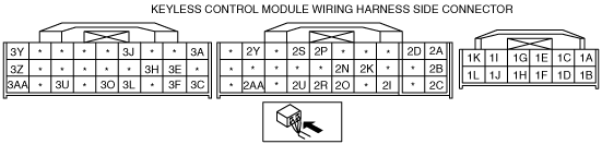
• Measure the voltage at the keyless control module terminals 3H, 3J and 3L while operating the request switch.
-
― Operate driver’s side front door request switch (3H): 5.0 V→1.0 V or less
― Operate passenger’s side front door request switch (3J): 5.0 V→1.0 V or less
― Operate liftgate request switch (3L): 5.0 V→1.0 V or less
• Is the voltage as above?
|
Yes
|
Go to the next step.
|
|
No
|
Inspect and repair the applicable wiring harness as necessary, then go to the next step.
|
|
6
|
• Measure the voltage at the following keyless control module terminal while operating the request switch.
-
― Terminal 1A and 1B for driver’s side keyless antenna
― Terminal 1C and 1D for passenger’s side keyless antenna
― Terminal 1E and 1F for exterior, rear keyless antenna
― Terminal 1G and 1H for interior, rear (4SD)/interior, RR (5HB, WGN) keyless antenna
― Terminal 1I and 1J for interior, RL keyless antenna (5HB, WGN)
― Terminal 1K and 1L for interior, middle keyless antenna
― Terminal 2G and 2H for interior, front keyless antenna
• Is the voltage within 4.0—6.0 V?
|
Yes
|
Go to the next step.
|
|
No
|
• Inspect for open or short circuit between suspect keyless antenna and keyless control module.
-
― If the wiring harness normal, replace suspect keyless antenna, then go to the next step.
― If the wiring harness is not normal, repair or replace for open or short circuit, then go to the next step.
|
|
7
|
• Disconnect the keyless receiver connector and keyless control module connector.
• Inspect the wiring harness between the following terminals for an open or short circuit.
-
― Terminal A — Terminal 2S
― Terminal C — Terminal 2U
― Terminal E — GND
• Is the wiring harness normal?
|
Yes
|
Go to the next step.
|
|
No
|
Inspect and repair the wiring harness between the keyless control module and the keyless receiver, then go to the next step.
|
|
8
|
• Measure the signal wave pattern for keyless control module terminal 2U using an oscilloscope when any of the request switches and the liftgate opener switch are operated.
• Does the wave pattern change when the request switch is operated?
-
Note
-
• Perform the oscilloscope setting using 0.5V/DIV (Y), 100 ms/DIV (X), DC range.
|
Yes
|
Go to the next step.
|
|
No
|
Replace the keyless receiver, and then go to Step 10.
|
|
9
|
• Measure the voltage at the keyless control module terminals 2R (BCM) while operating the request switch.
-
― Unlock: 1.0 V or less→B+→1.0 V or less
• Is the voltage as above?
|
Yes
|
Inspect and repair the wiring harness between the BCM and the keyless control module, then go to the next step.
|
|
No
|
Inspect the keyless control module. If the keyless control module is malfunctioning, replace the module.
|
|
10
|
• Does the keyless entry system operate properly?
|
Yes
|
Troubleshooting completed. Explain repairs to the customers
|
|
No
|
Re-inspect the malfunction symptoms, then repeat form Step 1 if malfunction recurs.
|