|
STEP
|
INSPECTION
|
ACTION
|
|
1
|
CHECK HORN, AND HAZARD WARNING LIGHT OPERATION DURING ON-BOARD DIAGNOSIS
• Did all of the following items work during on-board diagnostic function operation?
-
- Hazard warning lights flashed
|
Yes
|
Go to Step 5.
|
|
No
|
Go to next step.
|
|
2
|
INSPECT HAZARD WARNING LIGHT OPERATION DURING ON-BOARD DIAGNOSIS
• Did hazard warning lights flash during on-board diagnostic function operation?
|
Yes
|
Go to Step 5.
|
|
No
|
Go to next step.
|
|
3
|
INSPECT HAZARD WARNING LIGHT CIRCUIT
• Do hazard warning lights flash when hazard warning switch is on?
|
Yes
|
Go to next step.
|
|
No
|
Inspect hazard warning light circuit.
|
|
*4
|
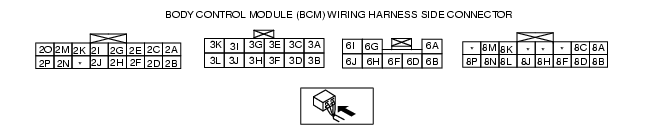
INSPECT IF MALFUNCTION IS IN WIRING HARNESS (BETWEEN BCM AND TURN LIGHTS) OR BCM
• Measure the voltage at BCM terminals 3B and 3D (12-pin connector), and 2I and 2K (16-pin connector), and 8H and 8J (16-pin connector) during on-board diagnostic function operation.
-
- When hazard warning light flashed: Alternates between B+ and below 1.0 V
• Are the voltage as above?
|
Yes
|
Recheck malfunction symptoms, then repeat from Step 1 if malfunction reoccurs.
|
|
No
|
• Inspect wiring harness between BCM and turn lights.
-
- If wiring harness is normal, replace the BCM, then go to Step 8.
-
- If wiring harness malfunction, repair wiring harness, then go to Step 8.
|
|
5
|
VERIFY THAT ALL DOORS LOCK AND UNLOCK DURING ON-BOARD DIAGNOSIS
• Do all doors unlock and lock during on-board diagnostic function operation?
|
Yes
|
Reinspect the malfunction symptoms, then repeat from Step 1 if the malfunction recurs.
|
|
No
|
Go to the next step.
|
|
6
|
INSPECT DOOR LOCK LINKAGE
• Operate the door lock knob and verify the door locks and unlocks manually.
• Does every door lock system work?
|
Yes
|
Go to the next step.
|
|
No
|
Inspect the door lock linkage.
|
|
*7
|
INSPECT IF MALFUNCTION IS IN DOOR LOCK ACTUATOR, BCM GROUND CIRCUIT OR ELSEWHERE
• Measure the voltage at BCM terminals 6A, 6B and 6F.
-
- All doors locked: 1.0 V or less → B+ → 1.0 V or less
-
(Normal lock: 6A terminal)
-
(Double lock: 6G terminal)
-
- Driver-side door unlocked: 1.0 V or less → B+ → 1.0 V or less
-
(Normal unlock: 6B terminal)
• Is the voltage as above?
|
Yes
|
Reinspect the malfunction symptoms, then repeat from Step 1 if the malfunction recurs.
|
|
No
|
• Inspect the BCM connector.
• Inspect the wiring harness between the BCM and door lock actuator.
-
- If the above parts are normal, go to the next step.
-
- If any of above parts are malfunctioning, repair the malfunctioning part.
|
|
8
|
REINSPECT MALFUNCTION SYMPTOM AFTER REPAIR
• Does the keyless entry system operate properly?
|
Yes
|
• Troubleshooting completed.
• Explain repairs to the customer.
|
|
No
|
Reinspect the malfunction symptoms, then repeat from Step 1 if malfunction recurs.
|