 |
am6zzw00004752
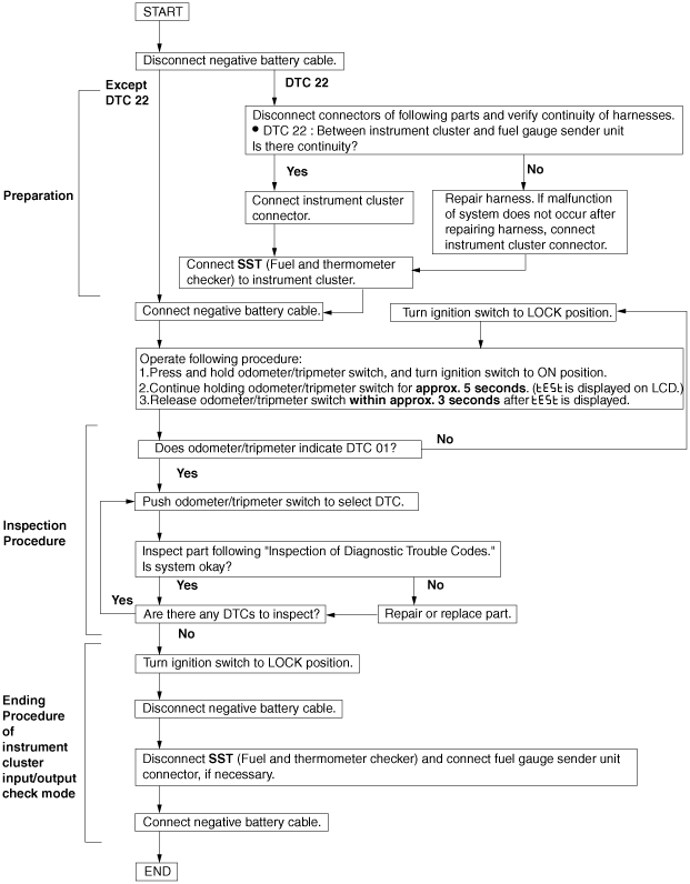
INSTRUMENT CLUSTER INPUT/OUTPUT CHECK MODE
id092200801700
Check Code Table
|
Check code |
Checked item |
Related item |
|---|---|---|
|
01
|
Buckle switch (driver-side)
|
Buckle switch (driver-side)
|
|
04
|
Door switch
|
• Ignition key illumination
• Key reminder warning buzzer
• Lights‐on reminder warning buzzer
|
|
08
|
TNS relay
|
• Lights‐on reminder warning buzzer
• Each illumination
|
|
12
|
Speedometer
|
Speedometer
|
|
13
|
Tachometer
|
Tachometer
|
|
14
|
Buzzer
|
Buzzer
|
|
16
|
Fuel‐level warning light
|
Fuel‐level warning light
|
|
22
|
Fuel gauge sender unit
|
Fuel gauge
|
|
23
|
Fuel gauge
|
Fuel gauge
|
|
25
|
Water temperature gauge
|
Water temperature gauge
|
|
26
|
LCD
|
LCD
|
|
31
|
Key reminder switch
|
Key reminder warning buzzer
|
|
33
|
Turn/hazard signal
|
Turn/hazard indicator buzzer
|
|
55
|
Dimmer cancel switch
|
Instrument cluster illumination
|
|
58
|
Buckle switch (passenger-side)
|
Buckle switch (passenger-side)
|
|
59
|
Fuel system signal
|
Fuel gauge
|
Operating Order
am6zzw00004752
|
Checking Order
|
Priority order of inspection |
IG switch position |
Check code |
|---|---|---|
|
1
|
ON
|
22
|
|
2
|
01, 04, 08, 12, 13, 14, 16, 23, 25, 26, 55, 58, 59
|
|
|
3
|
LOCK
|
31, 33
|
Inspection of Check Codes
Check code 01
|
Check code 01 |
Buckle switch (driver-side) on/off signal |
|||
|---|---|---|---|---|
 |
||||
Diagnostic procedure
|
STEP |
INSPECTION |
INDICATION |
ACTION |
|
|---|---|---|---|---|
|
1
|
Unfasten driver‐side seat belt. (Buckle switch on.)
|
 |
Go to next step.
|
|
 |
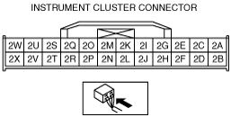
Measure voltage at instrument cluster terminal 2G.
Is voltage 0 V?
• If as specified, replace instrument cluster.
• If not as specified, inspect following parts.
|
|||
|
2
|
Fasten driver‐side seat belt. (Buckle switch off.)
|
|
Measure voltage at instrument cluster terminal 2G.
Is voltage B+?
• If as specified, replace instrument cluster.
• If not as specified, inspect following parts.
|
|
|
Input signal to instrument cluster is okay.
|
|||
Check code 04
|
Check code 04 |
Door switch on/off signal |
|||
|---|---|---|---|---|
 |
||||
Diagnostic procedure
|
STEP |
INSPECTION |
INDICATION |
ACTION |
|
|---|---|---|---|---|
|
1
|
Open driver‐side door. (Door switch on.)
|
|
Close driver‐side door, then go to next step.
|
|
|
Measure voltage at instrument cluster terminal 1J.
Is voltage 0 V?
• If as specified, replace instrument cluster.
• If not as specified, inspect following parts.
|
|||
|
2
|
Close driver‐side door. (Door switch off.)
|
|
Measure voltage at instrument cluster terminals 1J.
Is voltage B+?
• If as specified, replace instrument cluster.
• If not as specified, inspect following parts.
|
|
|
Input signal to instrument cluster is okay.
|
|||
Check code 08
|
Check code 08 |
TNS relay on/off signal |
|||
|---|---|---|---|---|
|
||||
Diagnostic procedure
|
STEP |
INSPECTION |
INDICATION |
ACTION |
|
|---|---|---|---|---|
|
1
|
Turn headlight switch to TNS position. (TNS relay on.)
|
|
Go to next step.
|
|
|
Measure voltage at instrument cluster terminal 2K.
Is voltage B+?
• If as specified, replace instrument cluster.
• If not as specified, inspect following parts.
|
|||
|
2
|
Turn headlight switch off. (TNS relay off.)
|
|
Measure voltage at instrument cluster terminal 2K.
Is voltage 0 V?
• If as specified, replace instrument cluster.
• If not as specified, inspect following parts.
|
|
|
Input signal to instrument cluster is okay.
|
|||
Check code 12
|
Check code 12 |
Operation signal to speedometer |
|||
|---|---|---|---|---|
|
INSPECTION |
INDICATION |
SITUATION |
ACTION |
|
|
Wait for 2 seconds after selecting check code 12.
|
 |
Speedometer needle moves full scale then returns to 60 km/h or 60 MPH.
|
Speedometer is okay.
|
|
|
Other than stated above.
|
Replace instrument cluster.
|
|||
 |
—
|
|||
Check code 13
|
Check code 13 |
Operation signal to tachometer |
|||
|---|---|---|---|---|
|
INSPECTION |
INDICATION |
SITUATION |
ACTION |
|
|
Wait for 2 seconds after selecting check code 13.
|
|
Tachometer needle moves full scale then returns to 3,000 rpm.
|
Tachometer is okay.
|
|
|
Other than stated above.
|
Replace instrument cluster.
|
|||
|
—
|
|||
Check code 14
|
Check code 14 |
Operation signal to buzzer |
|||
|---|---|---|---|---|
|
INSPECTION |
INDICATION |
SITUATION |
ACTION |
|
|
Wait for 2 seconds after selecting check code 14.
|
 |
Buzzer sounds.
|
Buzzer is okay.
|
|
|
Buzzer does not sound.
|
Replace instrument cluster.
|
|||
Check code 16
|
Check code 16 |
Operation signal to fuel‐level warning light |
|||
|---|---|---|---|---|
|
INSPECTION |
INDICATION |
SITUATION |
ACTION |
|
|
Wait for 2 seconds after selecting check code 16.
|
 |
Fuel‐level warning light turns on and off three times.
|
Fuel‐level warning light is okay.
|
|
|
Other than stated above.
|
Replace instrument cluster.
|
|||
Check code 22
|
Check code 22 |
Fuel level signal |
|||
|---|---|---|---|---|
|
||||
Diagnostic procedure
|
STEP |
INSPECTION |
INDICATION |
ACTION |
|---|---|---|---|
|
1
|
Select check code 22 with fuel gauge sender unit connector disconnected.
|
 |
Go to next step.
|
|
Other than stated above.
|
Replace instrument cluster.
|
||
|
2
|
Connect instrument cluster terminals 2D and 2M.
|
 |
Go to next step.
|
|
Other than stated above.
|
Replace instrument cluster.
|
||
|
3
|
Using SST (Fuel and thermometer checker) or resistor, input 20 ohms between instrument cluster terminals 2D and 2M.
|
 |
Go to next step.
|
|
Other than stated above.
|
Replace instrument cluster.
|
||
|
4
|
Using SST (Fuel and thermometer checker) or resistor, input 60 ohms between instrument cluster terminals 2D and 2M.
|
 |
Go to next step.
|
|
Other than stated above.
|
Replace instrument cluster.
|
||
|
5
|
Using SST (Fuel and thermometer checker) or resistor, input 100 ohms between instrument cluster terminals 2D and 2M.
|
 |
Inspect fuel gauge sender unit.
|
|
Other than stated above.
|
Replace instrument cluster.
|
Check code 23
|
Check code 23 |
Operation signal to fuel gauge |
|||
|---|---|---|---|---|
|
INSPECTION |
INDICATION |
SITUATION |
ACTION |
|
|
Wait for 2 seconds after selecting check code 23.
|
|
Fuel gauge indicates in following order every 2 seconds.
• F→1/2→E→F (fixed)
|
Fuel gauge is okay.
|
|
|
Other than stated above.
|
Replace instrument cluster.
|
|||
|
Replace instrument cluster.
|
|||
Check code 25
|
Check code 25 |
Operation signal to water temperature gauge |
|||
|---|---|---|---|---|
|
INSPECTION |
INDICATION |
SITUATION |
ACTION |
|
|
Wait for 2 seconds after selecting check code 25.
|
|
Water temperature gauge indicates in following order for every 2 seconds.
• H→Center→C→H (fixed)
|
Water temperature gauge is okay.
|
|
|
Other than stated above.
|
Replace instrument cluster.
|
|||
|
Replace instrument cluster.
|
|||
Check code 26
|
Check code 26 |
LCD indication |
|||
|---|---|---|---|---|
|
INSPECTION |
INDICATION |
SITUATION |
ACTION |
|
|
Select check code 26.
|
 |
• Display is normal.
• Warning and indicator light illuminated.
|
LCD is okay.
|
|
|
Other than stated above.
|
Replace instrument cluster.
|
|||
Check code 31
|
Check code 31 |
Key reminder on/off signal |
|||
|---|---|---|---|---|
|
||||
Diagnostic procedure
|
STEP |
INSPECTION |
INDICATION |
ACTION |
|
|---|---|---|---|---|
|
1
|
Turn the headlight switch to the TNS position.
Remove key from steering lock and then insert key into steering lock after selecting check code 31. (Key reminder switch on.)
|
|
Go to next step.
|
|
|
Measure voltage at instrument cluster terminal 2B.
Is voltage B+?
• If as specified, replace instrument cluster.
• If not as specified, replace following parts.
|
|||
|
2
|
Remove key from steering lock. (Key reminder switch off.)
|
|
Measure voltage at instrument cluster terminal 2B.
Is voltage 0 V?
• If as specified, replace instrument cluster.
• If not as specified, inspect following parts.
|
|
|
Input signal to instrument cluster is okay.
|
|||
Check code 33
|
Check code 33 |
Turn/hazard signal |
|||
|---|---|---|---|---|
|
||||
Diagnostic procedure
|
STEP |
INSPECTION |
INDICATION |
ACTION |
|
|---|---|---|---|---|
|
1
|
Turn the headlight switch to the TNS position.
Trun the hazard warning switch to on.
|
 |
Go to next step.
|
|
|
Measure voltage at instrument cluster terminal 2N.
Is voltage B+?
• If as specified, replace instrument cluster.
• If not as specified, replace following parts.
|
|||
|
2
|
Trun hazard warning switch off.
|
|
Input signal to instrument cluster is okay.
|
|
 |
Measure voltage at instrument cluster terminal 2N.
Is voltage below 1.0 v?
• If as specified, replace instrument cluster.
• If not as specified, replace following parts.
|
|||
Check code 55
|
Check code 55 |
Dimmer cancel switch on/off signal |
|||
|---|---|---|---|---|
|
||||
Diagnostic procedure
|
STEP |
INSPECTION |
INDICATION |
ACTION |
|
|---|---|---|---|---|
|
1
|
Turn the panel light control switch to the dimmer cancel position after selecting check code 55.
|
|
Go to next step.
|
|
|
Measure voltage at instrument cluster terminal 2A.
Is voltage 4 V?
• If as specified, replace instrument cluster.
• If not as specified, inspect following parts.
|
|||
|
2
|
Turn the panel light control switch to the other position.
|
|
Measure voltage at instrument cluster terminal 2A.
Is voltage 0 V?
• If as specified, replace instrument cluster.
• If not as specified, inspect following parts.
|
|
|
Input signal to instrument cluster is okay.
|
|||
Check code 58
|
Check code 58 |
Buckle switch (passenger-side) on/off signal |
|||
|---|---|---|---|---|
|
||||
Diagnostic procedure
|
STEP |
INSPECTION |
INDICATION |
ACTION |
|
|---|---|---|---|---|
|
1
|
Seat one person in the passenger’s seat, and unfasten passenger-side seat belt. (Occupancy sensor and buckle switch ON)
|
|
Go to next step.
|
|
|
Measure voltage at instrument cluster terminal 1A.
Is voltage 0 V?
• If as specified, replace instrument cluster.
• If not as specified, inspect following parts.
|
|||
|
2
|
Seat one person in the passenger’s seat, and fasten passenger-side seat belt. (Occupancy sensor ON and buckle switch OFF)
Seat no person in the passenger’s seat, and unfasten passenger-side seat belt. (Occupancy sensor OFF and buckle switch ON)
Seat no person in the passenger’s seat, and fasten passenger-side seat belt. (Occupancy sensor and buckle switch OFF)
|
|
Measure voltage at instrument cluster terminal 1A.
Is voltage B+?
• If as specified, replace instrument cluster.
• If not as specified, inspect following parts.
|
|
|
Input signal to instrument cluster is okay.
|
|||
Check code 59
Diagnostic procedure
|
STEP |
INSPECTION |
INDICATION |
ACTION |
|
|---|---|---|---|---|
|
1
|
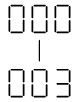
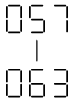
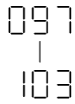
The three digits number is indicated after selecting check code 59. Confirm the first digit from the right.
|
 |
The CAN system is okay.
Go to next step.
|
|
 |
The DTC of CAN system is detected.
Perform the DTC inspection. (See DTC TABLE [MULTIPLEX COMMUNICATION SYSTEM])
• If the CAN system is okay, replace the instrument cluster.
Go to next step.
|
|||
|
2
|
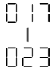
Confirm the second digit from the right.
|
 |
The wiring harnesses between the fuel gauge sender unit and instrument cluster are okay.
Go to next step.
|
|
 |
Inspect following parts.
• Fuel gauge sender unit
• Wiring harness (Fuel gauge sender unit—instrument cluster)
Go to next step.
|
|||
|
3
|
Confirm the third digit from the right.
|
 |
The fuel pulse signal from the PCM is okay.
|
|
 |
Inspect the PCM.
(See DTC TABLE [L8, LF, L3].)
(See DTC TABLE [MZR-CD (RF Turbo)].))
(See PCM INSPECTION [L8, LF, L3].)
• If the PCM is okay, replace the instrument cluster.
|
|||