 |
am6zzw00018619
FUEL GAUGE SENDER UNIT REMOVAL/INSTALLATION [4WD]
id0922008019b3
Fuel Gauge Sender Unit
1. Remove the fuel gauge sender unit. (See FUEL PUMP UNIT REMOVAL/INSTALLATION [L3 4WD].)
2. Install in the reverse order of removal.
Fuel Gauge Sender Sub-Unit
1. Complete the “BEFORE REPAIR PROCEDURE”.
2. Remove the plug hole plate.
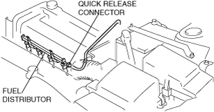
3. Disconnect the quick release connector connected to the fuel distributor.
am6zzw00018619
|
4. Connect a long hose to the disconnected quick release connector and drain the fuel into a container used for collecting gasoline.
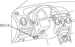
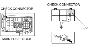
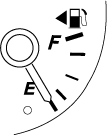
5. Start the fuel pump using the following procedure.
am6zzw00018611
|
am6zzw00018612
|
am6zzw00018613
|
6. Stop operation of the fuel pump when essentially no fuel is being discharged.
7. Reconnect the quick release connector to the fuel distributor.
8. Start the engine and idle it for 15 min (to transfer fuel from the sub-tank to the main tank).
9. Stop the engine.
10. Complete the “BEFORE REPAIR PROCEDURE”.
11. Remove the plug hole plate.
12. Disconnect the quick release connector connected to the fuel distributor.
am6zzw00018619
|
13. Connect a long hose to the disconnected quick release connector and drain the fuel into a container used for collecting gasoline.
14. Start the fuel pump using the following procedure.
am6zzw00018611
|
am6zzw00018612
|
am6zzw00018614
|
15. Stop operation of the fuel pump when essentially no fuel is being discharged.
16. Disconnect the negative battery cable.
17. Complete the following in order to the work area.
18. Remove the rear seat cushion.
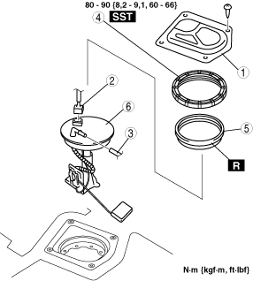
19. Remove in the order indicated in the table.
am6zzw00018615
|
|
1
|
Service hole cover
|
|
2
|
Connector
|
|
3
|
Plastic fuel hose (fuel tank side, transfer hose part)
|
|
4
|
Fuel gauge sender cap
|
|
5
|
Packing
|
|
6
|
Fuel gauge sender sub-unit
|
20. Install in the reverse order of removal.
21. Complete the “AFTER REPAIR PROCEDURE”.
22. Complete the “Fuel leak inspection after fuel gauge sender sub-unit installation.“ (See Fuel leak inspection after fuel gauge sender sub-unit installation.)
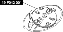
Fuel gauge sender cap removal note
1. Using the SST, remove the fuel gauge sender cap.
am6zzw00018616
|
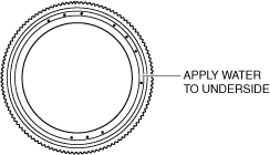
Fuel Gauge Sender Cap Installation Note
1. Apply water to the entire underside of the fuel pump cap.
am6zzw00018617
|
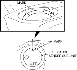
2. Verify that the fuel tank mark is aligned with the fuel gauge sender sub-unit mark as shown.
am6zzw00018618
|
3. Using the SST, tighten the fuel gauge sender cap without shifting the mark.
Fuel leak inspection after fuel gauge sender sub-unit installation
1. Drive the vehicle.
2. Perform a quick start and a hard brake 5—6 times.
3. Stop the vehicle.
4. Verify that there is no fuel leakage near the fuel pump unit in the vehicle interior.