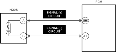
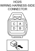
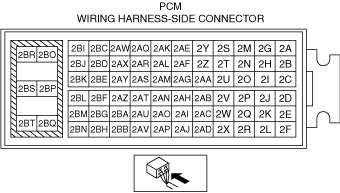
• To determine the malfunctioning part, proceed with the diagnostics from "Function Inspection Using M-MDS".
Details On DTCs
Description
HO2S circuit low input
Detection condition
Determination conditions
• A condition in which the HO2S input voltage is less than the specified value continues for the specified period.
Preconditions
• HO2S is activated.
• The following DTCs are not detected:
― MAF sensor: P0100:00, P0101:00 and U060F:00
― ECT sensor No.1: P0117:00 and P0118:00
Malfunction determination period
• 5 s period
Drive cycle
• 2
Self test type
• CMDTC self test
Sensor used
• HO2S
Fail-safe function
• Fixes duty value of A/F sensor heater
• Stops fuel feedback control of A/F sensor
Vehicle status when DTCs are output
• Not applicable
Possible cause
• HO2S connector or terminals malfunction
• PCM connector or terminals malfunction
• Short to ground in HO2S signal (+) circuit
• Open circuit in any of the following HO2S circuits.
― Signal (+) circuit
― Signal (−) circuit
• HO2S malfunction
• PCM malfunction
Function Explanation (DTC Detection Outline)
• The PCM detects the oxygen concentration in the exhaust gas based on the HO2S signal. The PCM determines a HO2S signal error based on the condition in which the HO2S input voltage continues to be less than the specified value, and stores a DTC.
Repeatability Verification Procedure
1. Warm up the engine to allow the engine coolant temperature to reach 80 °C {176 °F} or more.
2. Start the engine and leave it idling for 1 min.
Note
• Match the engine coolant temperature in the recorded freeze frame data/snapshot data, the vehicle speed, and engine speed values to the best extent possible while driving the vehicle.
3. Try to reproduce the malfunction by driving the vehicle for 5 min based on the values in the freeze frame data/snapshot data.
PID Item/Simulation Item Used In Diagnosis
• Not applicable
Function Inspection Using M-MDS
Step
Inspection
Results
Action
1
PURPOSE: VERIFY RELATED REPAIR INFORMATION OR SERVICE INFORMATION AVAILABILITY
• Verify related Service Bulletins, on-line repair information, or Service Information availability.
• Is any related Information available?
Yes
Perform repair or diagnosis according to the available information.
• If the vehicle is not repaired, go to the next step.
No
Go to the next step.
2
PURPOSE: RECORD VEHICLE STATUS WHEN DTC WAS DETECTED TO UTILIZE WITH REPEATABILITY VERIFICATION
• Record the freeze frame data/snapshot data.
Note
• Recording can be facilitated using the screen capture function of the PC.
—
Go to Troubleshooting Diagnostic Procedure to perform the procedure from Step 1.
Troubleshooting Diagnostic Procedure
Intention of troubleshooting procedure
• Step 1—4
― Perform an inspection of the HO2S and PCM-related connectors and wiring harnesses.
• Step 5
― Perform a unit inspection of the HO2S.
• Repair completion verification
― Verify that the primary malfunction is resolved and there are no other malfunctions.