• There are two types of PCM settings. If the incorrect PCM is installed, it could cause interference with engine control.
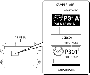
• When replacing the PCM, verify the first four digits of the part number indicated on the PCM label before replacement, and replace the PCM with one having the same part number.
am3zzw00027738
• When replacing the PCM, perform the configuration to assure that the system operates correctly. (See CONFIGURATION.)
1. When replacing the PCM, perform the configuration using the following procedure.
(1) Connect the M-MDS to the DLC-2.
(2) Switch the ignition ON (engine off).
(3) Activate the M-MDS and perform the following procedure.
1) Press [Start] to start the vehicle identification.
2) Press the [Toolbox] tab.
3) Press the [Work Support] icon.
4) Press [Configuration].
5) Press [Run] to perform the configuration.
6) Press [PCM].
7) Verify that the ignition is switched ON (engine off) and press [Next].
• If the ignition cannot be switched ON (engine off), leave it as it is and press [Next].
8) When [Install the new ECU] is displayed, move to the PCM replacement procedure.
6. If the PCM is replaced, perform the following procedure.
Note
• Depending on the vehicle conditions, the configuration after PCM replacement may use the data read from the PCM before replacement or the data as of shipment from manufacturer (As-Built data).
• The data used for the configuration is displayed on the lower part of the M-MDS display when the configuration is completed.
(1) Continue to perform configuration following the instructions on the M-MDS screen.
(4) If manual configuration is performed using the As-Built data, write the coupling component characteristic value. (AWD) (See COUPLING COMPONENT CALIBRATION DATA WRITING.)