DTC U2300:00 [PCM (SKYACTIV-D)]
id0102t5228300
Details On DTCs
| Description | Global central configuration error | ||
|---|---|---|---|
| Detection condition | Determination conditions | •  Any of following conditions occurs: 
 | |
| Preconditions | •  Battery voltage: 10.0 V*1or more  •  Switch the ignition ON (engine off or on) *1: Standard can be verified by displaying PIDs using M-MDS | ||
| Malfunction determination period | •  10 s period | ||
| Drive cycle | •  1 | ||
| Self test type | •  CMDTC self test, KOEO self test, KOER self test | ||
| Sensor used | •  PCM | ||
| Fail-safe function | •  Operates by the previously learned configuration value. | ||
| Vehicle status when DTCs are output | •  Not applicable | ||
| Possible cause | 
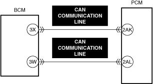
•  CAN drive error (body control module (BCM) or PCM) •  Configuration data for the body control module (BCM) is incorrectly set •  CAN communication line malfunction between body control module (BCM) and PCM 
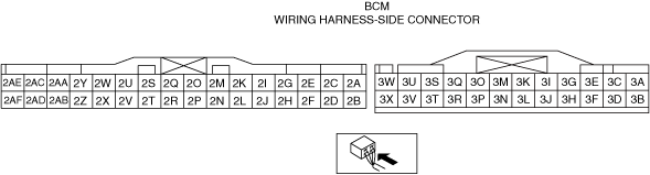
•  Body control module (BCM) connector or terminals malfunction 
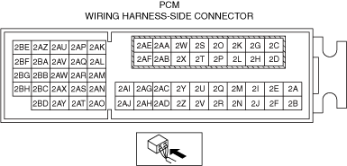
•  PCM connector or terminals malfunction •  Body control module (BCM) incorrect installation •  Body control module (BCM) malfunction •  Error in non-volatile memory in PCM •  PCM malfunction | ||
|  | |||
|  | |||
|  | |||
Function Explanation (DTC Detection Outline)
Repeatability Verification Procedure
PID Item/Simulation Item Used In Diagnosis
Function Inspection Using M-MDS
| Step | Inspection | Results | Action | 
|---|---|---|---|
| 1 | PURPOSE: VERIFY RELATED REPAIR INFORMATION OR SERVICE INFORMATION AVAILABILITY •  Verify related Service Bulletins, on-line repair information, or Service Information availability. •  Is any related Information available? | Yes | Perform repair or diagnosis according to the available information. •  If the vehicle is not repaired, go to the next step. | 
| No | Go to the next step. | ||
| 2 | PURPOSE: RECORD VEHICLE STATUS WHEN DTC WAS DETECTED TO UTILIZE WITH REPEATABILITY VERIFICATION •  Record the freeze frame data/snapshot data. 
 | — | Go to the next step. | 
| 3 | PURPOSE: INSPECT FOR OTHER RELATED DTCs •  Perform the DTC inspection for the PCM. (See DTC INSPECTION.) •  Are any of the following DTCs displayed? 
 PCM: | Yes | Repair the malfunctioning location according to the applicable DTC troubleshooting. Go to the next step. | 
| No | Go to the next step. | ||
| 4 | PURPOSE: VERIFY BODY CONTROL MODULE (BCM) DTC •  Perform the DTC inspection for the body control module (BCM). (See DTC INSPECTION.) •  Are any DTCs displayed? | Yes | Repair the malfunctioning location according to the applicable DTC troubleshooting. Go to Troubleshooting Diagnostic Procedure to perform the procedure from Step 1. | 
| No | Go to Troubleshooting Diagnostic Procedure to perform the procedure from Step 1. | 
Troubleshooting Diagnostic Procedure
| Step | Inspection | Results | Action | 
|---|---|---|---|
| 1 | PURPOSE: INSPECT BODY CONTROL MODULE (BCM) CONNECTOR FOR MALFUNCTION •  Inspect the applicable connector and terminal. (See CONNECTOR INSPECTION.) •  Are the connector and terminal normal? | Yes | Go to the next step. | 
| No | Repair or replace the malfunctioning location and perform the repair completion verification. | ||
| 2 | PURPOSE: INSPECT PCM CONNECTOR FOR MALFUNCTION •  Inspect the applicable connector and terminal. (See CONNECTOR INSPECTION.) •  Are the connector and terminal normal? | Yes | Go to the next step. | 
| No | Repair or replace the malfunctioning location and perform the repair completion verification. | ||
| 3 | PURPOSE: VERIFY IF BODY CONTROL MODULE (BCM) IS INSTALLED CORRECTLY •  Verify the body control module (BCM) installation condition.
 •  Is the installation condition normal? | Yes | Go to the next step. | 
| No | Correctly install the body control module (BCM) and perform the repair completion verification. | ||
| 4 | PURPOSE: INSPECT BODY CONTROL MODULE (BCM) FOR MALFUNCTION •  Inspect the applicable part.
 •  Is the part normal? | Yes | Go to the next step. | 
| No | Repair or replace the malfunctioning location and perform the repair completion verification. | ||
| Repair completion verification 1 | PURPOSE: VERIFY THAT VEHICLE IS REPAIRED •  Install/connect the part removed/disconnected during the troubleshooting procedure. •  Clear the DTC recorded in the memory. (See CLEARING DTC.) •  Replicate the vehicle conditions at the time the DTC was detected using the following procedure. 
 •  Perform the DTC inspection for the PCM. (See DTC INSPECTION.) •  Is the same Pending DTC present? | Yes | Refer to the controller area network (CAN) malfunction diagnosis flow to inspect for a CAN communication error. If the CAN communication is normal, perform the diagnosis from Step 1. •  If the malfunction recurs, replace the PCM, then go to the next step.
 | 
| No | Go to the next step. | ||
| Repair completion verification 2 | PURPOSE: VERIFY IF OTHER DTCs DISPLAYED •  Perform the DTC inspection. (See DTC INSPECTION.) •  Are any other DTCs displayed? | Yes | Repair the malfunctioning location according to the applicable DTC troubleshooting. | 
| No | DTC troubleshooting completed. |