1. If the PCM is replaced, perform the following procedure.
Note
• Depending on the vehicle conditions, the configuration after PCM replacement may use the data read from the PCM before replacement or the data as of shipment from manufacturer (As-Built data).
• The data used for the configuration is displayed on the lower part of the M-MDS display when the configuration is completed.
(1) Continue to perform configuration following the instructions on the M-MDS screen.
(2) If manual configuration is performed using the As-Built data, perform the following procedure.
• Because the PCM is new, it is not necessary to perform the engine oil data reset.
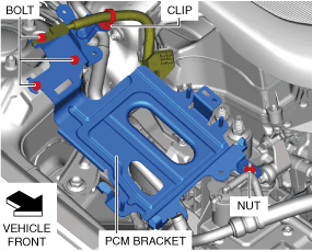
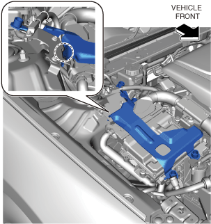
PCM Bracket Installation Note
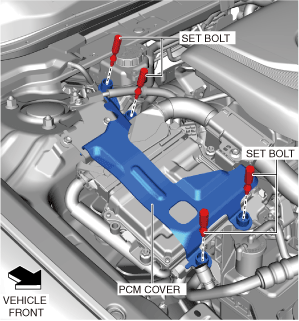
1. Install the PCM bracket using the following procedure:
am3zzw00031151
(1) Temporarily tighten bolt A.
(2) Install bolt B.
(3) Install the nut.
(4) Tighten bolt A.
(5) Install bolt C.
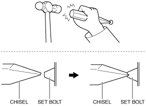
Set Bolt Removal Note
1. Using a chisel and a hammer, cut a groove on the head of the set bolt so that a screwdriver can be inserted.
2. Loose the set bolt using an impact screwdriver or pliers.
am6zzw00010942
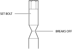
Set Bolt Installation Note
1. Install a new set bolt and tighten it until the neck of the bolt breaks off.
ac3wzw00001337
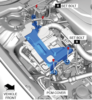
PCM Cover Installation Note
1. Install the PCM cover as shown in the figure.
am3zzw00034407
2. Temporarily tighten the four bolts, then completely tighten them.
am3zzw00034408
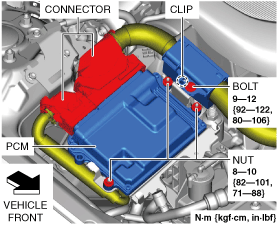
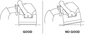
PCM Connector Connection Note
Caution
• Do not touch the PCM connector terminal. The terminal is extremely thin and can be damaged by touching it.
• If the PCM connector is inserted at an angle and the lever is moved, the connector could be damaged. Verify that the PCM connector is inserted straight.
am3zzw00031170
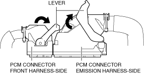
1. Set the PCM connector lever to the position shown in the figure.
am3zzw00031173
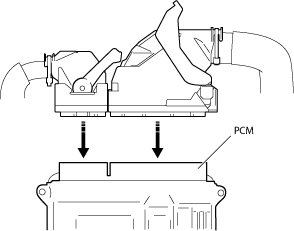
2. Align the PCM connector straight against the connection surface.
adejjw00012311
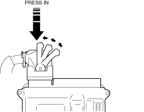
3. Insert the PCM connector straight and press it in until the lever moves up naturally. (Front harness-side connector)
am3zzw00034409
4. Press the PCM connector lever until a click sound is heard.