DTC P0642:00 [PCM (SKYACTIV-D)]
id0102t5315500
Outline
System malfunction location |
Constant voltage power supply circuit low input |
|||
---|---|---|---|---|
Detection condition
|
• When the following condition is met, the output voltage of the constant voltage (5 V) power supply terminal is less than 2.36 V for a continuous 0.5 s.
|
|||
Fail-safe
|
• PCM restricts engine torque.
• Limits the maximum engine speed.
• Inhibits the DENOx/DESOx control.
• Inhibits the diesel particulate filter regeneration control.
• Inhibits the EGR control.
• PCM restricts engine-transaxle integration control. (ATX)
• Inhibits engine-stop by operating the i-stop function.
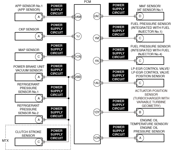
|
|||
Possible cause
|
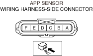
• APP sensor connector or terminal malfunction
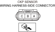
• CKP sensor connector or terminal malfunction
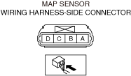
• MAP sensor connector or terminal malfunction
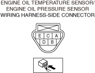
• Engine oil temperature/engine oil pressure sensor connector or terminal malfunction
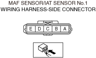
• MAF/IAT sensor No.1 connector or terminal malfunction
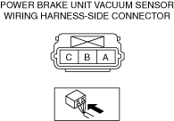
• Power brake unit vacuum sensor connector or terminal malfunction
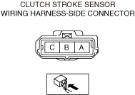
• Clutch stroke sensor connector or terminal malfunction (MTX)
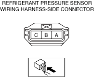
• Refrigerant pressure sensor No.1 connector or terminal malfunction
• Refrigerant pressure sensor No.2 connector or terminal malfunction
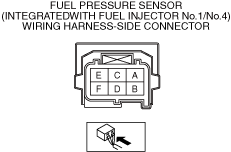
• Fuel pressure sensor (integrated with fuel injector No.1) connector or terminal malfunction
• Fuel pressure sensor (integrated with fuel injector No.4) connector or terminal malfunction
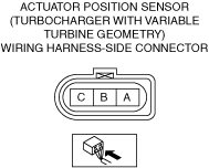
• Actuator position sensor (turbocharger) connector or terminal malfunction
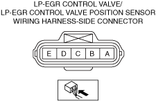
• LP-EGR control valve/LP-EGR control valve position sensor connector or terminal malfunction
• Short to ground in APP sensor power supply circuit
• Short to ground in CKP sensor power supply circuit
• Short to ground in MAP sensor power supply circuit
• Short to ground in engine oil temperature/engine oil pressure sensor power supply circuit
• Short to ground in MAF/IAT sensor No.1 power supply circuit
• Short to ground in Power brake unit vacuum sensor power supply circuit
• Short to ground in Clutch stroke sensor power supply circuit
• Short to ground in Refrigerant pressure sensor No.1 power supply circuit
• Short to ground in Refrigerant pressure sensor No.2 power supply circuit
• Short to ground in Fuel pressure sensor (integrated with fuel injector No.1) power supply circuit
• Short to ground in Fuel pressure sensor (integrated with fuel injector No.4) power supply circuit
• Short to ground in Actuator position sensor (turbocharger) power supply circuit
• Short to ground in LP-EGR control valve power supply circuit
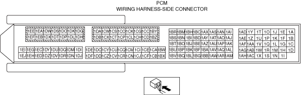
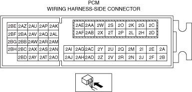
• PCM connector or terminal malfunction
• PCM malfunction
|
|||
![]() |
||||
![]() |
![]() |
![]() |
||
![]() |
![]() |
![]() |
||
![]() |
![]() |
|||
![]() |
![]() |
|||
![]() |
||||
![]() |
![]() |
Diagnostic Procedure
Step |
Inspection |
Results |
Action |
---|---|---|---|
1
|
RECORD VEHICLE STATUS WHEN DTC WAS DETECTED TO UTILIZE WITH REPEATABILITY VERIFICATION
• Record the freeze frame data/snapshot data.
|
—
|
Go to the next step.
|
2
|
VERIFY RELATED REPAIR INFORMATION OR SERVICE INFORMATION AVAILABILITY
• Verify related Service Bulletins, on-line repair information, or Service Information availability.
• Is any related Information available?
|
Yes
|
Perform repair or diagnosis according to the available information.
• If the vehicle is not repaired, go to the next step.
|
No
|
Go to the next step.
|
||
3
|
INSPECT FOR OTHER RELATED DTCs
• Perform the DTC inspection for the PCM.
(See DTC INSPECTION.)
• Are any other DTCs displayed?
|
Yes
|
Repair the malfunctioning location according to the applicable DTC troubleshooting.
(See DTC TABLE [PCM (SKYACTIV-D)].)
|
No
|
Go to the next step.
|
||
4
|
INSPECT PCM CONNECTOR FOR MALFUNCTION
• Inspect the applicable connector and terminal.
(See CONNECTOR INSPECTION.)
• Are the connector and terminal normal?
|
Yes
|
Go to the next step.
|
No
|
Repair or replace the malfunctioning location and perform the repair completion verification.
|
||
5
|
INSPECT APP SENSOR CONNECTOR FOR MALFUNCTION
• Inspect the applicable connector and terminal.
(See CONNECTOR INSPECTION.)
• Are the connector and terminal normal?
|
Yes
|
Go to the next step.
|
No
|
Repair or replace the malfunctioning location and perform the repair completion verification.
|
||
6
|
INSPECT CKP SENSOR CONNECTOR FOR MALFUNCTION
• Inspect the applicable connector and terminal.
(See CONNECTOR INSPECTION.)
• Are the connector and terminal normal?
|
Yes
|
Go to the next step.
|
No
|
Repair or replace the malfunctioning location and perform the repair completion verification.
|
||
7
|
INSPECT MAP SENSOR CONNECTOR FOR MALFUNCTION
• Inspect the applicable connector and terminal.
(See CONNECTOR INSPECTION.)
• Are the connector and terminal normal?
|
Yes
|
Go to the next step.
|
No
|
Repair or replace the malfunctioning location and perform the repair completion verification.
|
||
8
|
INSPECT ENGINE OIL TEMPERATURE/ENGINE OIL PRESSURE SENSOR CONNECTOR FOR MALFUNCTION
• Inspect the applicable connector and terminal.
(See CONNECTOR INSPECTION.)
• Are the connector and terminal normal?
|
Yes
|
Go to the next step.
|
No
|
Repair or replace the malfunctioning location and perform the repair completion verification.
|
||
9
|
INSPECT MAF/IAT SENSOR No.1 CONNECTOR FOR MALFUNCTION
• Inspect the applicable connector and terminal.
(See CONNECTOR INSPECTION.)
• Are the connector and terminal normal?
|
Yes
|
Go to the next step.
|
No
|
Repair or replace the malfunctioning location and perform the repair completion verification.
|
||
10
|
INSPECT POWER BRAKE UNIT VACUUM SENSOR CONNECTOR FOR MALFUNCTION
• Inspect the applicable connector and terminal.
(See CONNECTOR INSPECTION.)
• Are the connector and terminal normal?
|
Yes
|
MTX
• Go to the next step.
ATX
• Go to Step 12.
|
No
|
Repair or replace the malfunctioning location and perform the repair completion verification.
|
||
11
|
INSPECT CLUTCH STROKE SENSOR CONNECTOR FOR MALFUNCTION
• Inspect the applicable connector and terminal.
(See CONNECTOR INSPECTION.)
• Are the connector and terminal normal?
|
Yes
|
Go to the next step.
|
No
|
Repair or replace the malfunctioning location and perform the repair completion verification.
|
||
12
|
INSPECT REFRIGERANT PRESSURE SENSOR No.1 AND No.2 CONNECTOR FOR MALFUNCTION
• Inspect the applicable connector and terminal.
(See CONNECTOR INSPECTION.)
• Are the connector and terminal normal?
|
Yes
|
Go to the next step.
|
No
|
Repair or replace the malfunctioning location and perform the repair completion verification.
|
||
13
|
INSPECT FUEL PRESSURE SENSOR (INTEGRATED WITH FUEL INJECTOR No.1) CONNECTOR FOR MALFUNCTION
• Inspect the applicable connector and terminal.
(See CONNECTOR INSPECTION.)
• Are the connector and terminal normal?
|
Yes
|
Go to the next step.
|
No
|
Repair or replace the malfunctioning location and perform the repair completion verification.
|
||
14
|
INSPECT FUEL PRESSURE SENSOR (INTEGRATED WITH FUEL INJECTOR No.4) CONNECTOR FOR MALFUNCTION
• Inspect the applicable connector and terminal.
(See CONNECTOR INSPECTION.)
• Are the connector and terminal normal?
|
Yes
|
Go to the next step.
|
No
|
Repair or replace the malfunctioning location and perform the repair completion verification.
|
||
15
|
INSPECT VARIABLE TURBINE GEOMETRY TURBOCHARGER ACTUATOR POSITION SENSOR CONNECTOR FOR MALFUNCTION
• Inspect the applicable connector and terminal.
(See CONNECTOR INSPECTION.)
• Are the connector and terminal normal?
|
Yes
|
Go to the next step.
|
No
|
Repair or replace the malfunctioning location and perform the repair completion verification.
|
||
16
|
INSPECT LP-EGR CONTROL VALVE/LP-EGR CONTROL VALVE POSITION SENSOR CONNECTOR FOR MALFUNCTION
• Inspect the applicable connector and terminal.
(See CONNECTOR INSPECTION.)
• Are the connector and terminal normal?
|
Yes
|
Go to the next step.
|
No
|
Repair or replace the malfunctioning location and perform the repair completion verification.
|
||
17
|
INSPECT EACH POWER SUPPLY CIRCUIT FOR SHORT TO GROUND
• Inspect the applicable circuit for a short to ground.
(See CIRCUIT INSPECTION.)
• Is the circuit normal?
|
Yes
|
Go to the next step.
|
No
|
Repair or replace the malfunctioning location and perform the repair completion verification.
|
||
Repair completion verification 1
|
VERIFY THAT VEHICLE IS REPAIRED
• Install/connect the part removed/disconnected during the troubleshooting procedure.
• Clear the DTC recorded in the memory.
(See CLEARING DTC.)
• Replicate the vehicle conditions at the time the DTC was detected using the following procedure.
• Perform the DTC inspection for the PCM.
(See DTC INSPECTION.)
• Is the same Pending DTC present?
|
Yes
|
Refer to the controller area network (CAN) malfunction diagnosis flow to inspect for a CAN communication error.
If the CAN communication is normal, perform the diagnosis from Step 1.
• If the malfunction recurs, replace the PCM, then go to the next step.
|
No
|
Go to the next step.
|
||
Repair completion verification 2
|
VERIFY IF OTHER DTCs DISPLAYED
• Perform the DTC inspection.
(See DTC INSPECTION.)
• Are any other DTCs displayed?
|
Yes
|
Repair the malfunctioning location according to the applicable DTC troubleshooting.
|
No
|
DTC troubleshooting completed.
|