DTC U0323:00 [PCM (SKYACTIV-D)]
DTC U0323:00 [PCM (SKYACTIV-D)]
id0102t5901400
-
Note
-
• To determine the malfunctioning part, proceed with the diagnostics from "Function Inspection Using M-MDS".
Details On DTCs
|
Description
|
Instrument cluster error
|
|
Detection condition
|
Determination conditions
|
• The following errors (signal value error) occur in the CAN communication with the PCM and body control module (BCM).
-
― Check sum error in signal from Instrument cluster
― Counter error in signal from Instrument cluster
|
|
Preconditions
|
• The following conditions continue for 1.5 s:
-
― Battery voltage: 10 V *1or more
― Switch the ignition ON (engine off or on)
*1: Standard can be verified by displaying PIDs using M-MDS
|
|
Malfunction determination period
|
• 5 s period
|
|
Drive cycle
|
• 1
|
|
Self test type
|
• CMDTC self test
|
|
Sensor used
|
• PCM
|
|
Fail-safe function
|
• Not applicable
|
|
Vehicle status when DTCs are output
|
• Not applicable
|
|
Possible cause
|
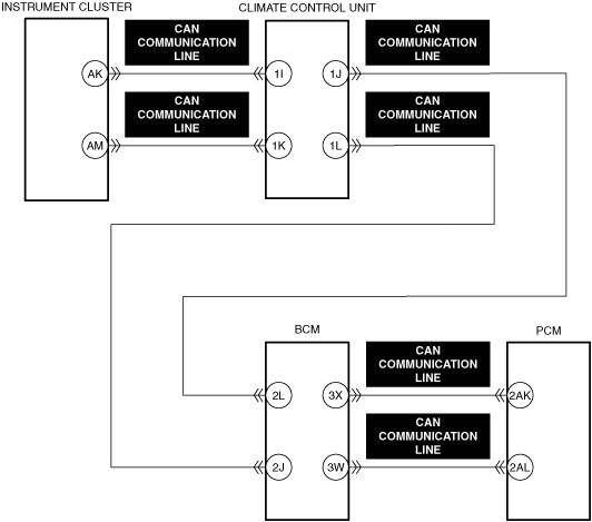
• CAN communication line malfunction between Instrument cluster and PCM
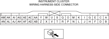
• Instrument cluster connector or terminals malfunction
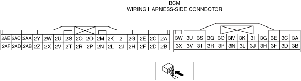
• Body control module (BCM) connector or terminals malfunction
• PCM connector or terminals malfunction
• Instrument cluster malfunction
• Body control module (BCM) malfunction
• PCM malfunction
|
 |
 |
 |
 |
 |
Function Explanation (DTC Detection Outline)
• The PCM detects a DTC if the following errors (signal value error) occur in the CAN communication with the PCM and body control module (BCM).
-
― Check sum error in signal from Instrument cluster
― Counter error in signal from Instrument cluster
Repeatability Verification Procedure
1. Switch the ignition ON (engine off or on) and wait for 10 s or more.
PID Item/Simulation Item Used In Diagnosis
• Not applicable
Function Inspection Using M-MDS
|
Step
|
Inspection
|
Results
|
Action
|
|
1
|
PURPOSE: VERIFY RELATED REPAIR INFORMATION OR SERVICE INFORMATION AVAILABILITY
• Verify related Service Bulletins, on-line repair information, or Service Information availability.
• Is any related Information available?
|
Yes
|
Perform repair or diagnosis according to the available information.
• If the vehicle is not repaired, go to the next step.
|
|
No
|
Go to the next step.
|
|
2
|
PURPOSE: RECORD VEHICLE STATUS WHEN DTC WAS DETECTED TO UTILIZE WITH REPEATABILITY VERIFICATION
• Record the freeze frame data/snapshot data.
-
Note
-
• Recording can be facilitated using the screen capture function of the PC.
|
—
|
Go to the next step.
|
|
3
|
PURPOSE: INSPECT FOR OTHER RELATED DTCs
• Perform the DTC inspection for the PCM.
• Are any other DTCs displayed?
|
Yes
|
Repair the malfunctioning location according to the applicable DTC troubleshooting.
Go to the next step.
|
|
No
|
Go to the next step.
|
|
4
|
PURPOSE: INSPECT FOR OTHER RELATED DTCs
• Perform the DTC inspection for the Instrument cluster.
• Are any other DTCs displayed?
|
Yes
|
Repair the malfunctioning location according to the applicable DTC troubleshooting.
Go to Troubleshooting Diagnostic Procedure to perform the procedure from Step 1.
|
|
No
|
Go to Troubleshooting Diagnostic Procedure to perform the procedure from Step 1.
|
Troubleshooting Diagnostic Procedure
Intention of troubleshooting procedure
• Step 1—2
-
― Perform an inspection of the instrument cluster and PCM-related connectors.
• Repair completion verification
-
― Verify that the primary malfunction is resolved and there are no other malfunctions.
|
Step
|
Inspection
|
Results
|
Action
|
|
1
|
PURPOSE: INSPECT INSTRUMENT CLUSTER CONNECTOR FOR MALFUNCTION
• Inspect the applicable connector and terminal.
• Are the connector and terminal normal?
|
Yes
|
Go to the next step.
|
|
No
|
Repair or replace the malfunctioning location and perform the repair completion verification.
|
|
2
|
PURPOSE: INSPECT PCM CONNECTOR FOR MALFUNCTION
• Inspect the applicable connector and terminal.
• Are the connector and terminal normal?
|
Yes
|
Go to the next step.
|
|
No
|
Repair or replace the malfunctioning location and perform the repair completion verification.
|
|
Repair completion verification 1
|
PURPOSE: VERIFY THAT VEHICLE IS REPAIRED
• Install/connect the part removed/disconnected during the troubleshooting procedure.
• Clear the DTC recorded in the memory.
• Replicate the vehicle conditions at the time the DTC was detected using the following procedure.
-
― Implement the repeatability verification procedure.
• Perform the DTC inspection for the PCM.
• Is the same Pending DTC present?
|
Yes
|
Refer to the controller area network (CAN) malfunction diagnosis flow to inspect for a CAN communication error.
If the CAN communication is normal, perform the diagnosis from Step 1.
• If the malfunction recurs, replace the PCM, then go to the next step.
|
|
No
|
Go to the next step.
|
|
Repair completion verification 2
|
PURPOSE: VERIFY IF OTHER DTCs DISPLAYED
• Perform the DTC inspection.
• Are any other DTCs displayed?
|
Yes
|
Repair the malfunctioning location according to the applicable DTC troubleshooting.
|
|
No
|
DTC troubleshooting completed.
|