|
1
|
RECORD VEHICLE STATUS WHEN DTC WAS DETECTED TO UTILIZE WITH REPEATABILITY VERIFICATION
• Record the freeze frame data/snapshot data.
-
Note
-
• Recording can be facilitated using the screen capture function of the PC.
|
—
|
Go to the next step.
|
|
2
|
VERIFY RELATED REPAIR INFORMATION OR SERVICE INFORMATION AVAILABILITY
• Verify related Service Bulletins, on-line repair information, or Service Information availability.
• Is any related Information available?
|
Yes
|
Perform repair or diagnosis according to the available information.
• If the vehicle is not repaired, go to the next step.
|
|
No
|
Go to the next step.
|
|
3
|
VERIFY DTCs
• Perform the DTC inspection for the following modules.
-
― PCM
― Mazda M Hybrid battery
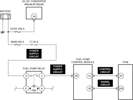
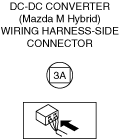
― DC-DC converter (Mazda M Hybrid)
― Integrated starter generator (ISG)
• Are any DTCs displayed?
|
Yes
|
Repair the malfunctioning location according to the applicable DTC troubleshooting.
|
|
No
|
Go to the next step.
|
|
4
|
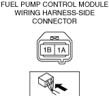
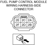
INSPECT FUEL PUMP CONTROL MODULE CONNECTOR FOR MALFUNCTION
• Inspect the applicable connector and terminal.
• Are the connector and terminal normal?
|
Yes
|
Go to the next step.
|
|
No
|
Repair or replace the malfunctioning location and perform the repair completion verification.
|
|
5
|
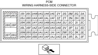
INSPECT PCM CONNECTOR FOR MALFUNCTION
• Inspect the applicable connector and terminal.
• Are the connector and terminal normal?
|
Yes
|
Go to the next step.
|
|
No
|
Repair or replace the malfunctioning location and perform the repair completion verification.
|
|
6
|
INSPECT FUEL PUMP CONTROL MODULE SIGNAL CIRCUIT FOR SHORT TO POWER SUPPLY
• Inspect the applicable circuit for a short to power supply.
• Is the circuit normal?
|
Yes
|
Go to the next step.
|
|
No
|
Repair or replace the malfunctioning location and perform the repair completion verification.
|
|
7
|
INSPECT FUEL PUMP CONTROL MODULE SIGNAL CIRCUIT FOR OPEN CIRCUIT
• Inspect the applicable circuit for open circuit.
• Is the circuit normal?
|
Yes
|
Go to the next step.
|
|
No
|
Repair or replace the malfunctioning location and perform the repair completion verification.
|
|
8
|
INSPECT FUEL PUMP CONTROL MODULE FOR MALFUNCTION
• Inspect the applicable part.
• Is the part normal?
|
Yes
|
Go to the next step.
|
|
No
|
Repair or replace the malfunctioning location and perform the repair completion verification.
|
|
9
|
INSPECT FUEL PUMP CONTROL MODULE POWER SUPPLY CIRCUIT FOR SHORT TO GROUND
• Inspect the applicable circuit for a short to ground.
• Is the circuit normal?
|
Yes
|
Go to the next step.
|
|
No
|
Repair or replace the malfunctioning location and perform the repair completion verification.
|
|
10
|
INSPECT FUEL PUMP CONTROL MODULE POWER SUPPLY CIRCUIT FOR SHORT TO POWER SUPPLY
• Inspect the applicable circuit for a short to power supply.
• Is the circuit normal?
|
Yes
|
Go to the next step.
|
|
No
|
Repair or replace the malfunctioning location and perform the repair completion verification.
|
|
11
|
INSPECT FUEL PUMP CONTROL MODULE POWER SUPPLY CIRCUIT FOR OPEN CIRCUIT
• Inspect the applicable circuit for open circuit.
• Is the circuit normal?
|
Yes
|
Go to the next step.
|
|
No
|
Repair or replace the malfunctioning location and perform the repair completion verification.
|
|
12
|
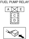
INSPECT FUEL PUMP RELAY FOR MALFUNCTION
• Inspect the applicable part.
• Is the part normal?
|
Yes
|
Go to the next step.
|
|
No
|
Repair or replace the malfunctioning location and perform the repair completion verification.
|
|
13
|
INSPECT FUEL PUMP RELAY POWER SUPPLY CIRCUIT FOR SHORT TO GROUND AND OPEN CIRCUIT
• Inspect the power supply circuit for an open circuit and short to ground.
• Is the circuit normal?
|
Yes
|
Go to the next step.
|
|
No
|
Repair or replace the malfunctioning location and perform the repair completion verification.
|
|
Repair completion verification 1
|
VERIFY THAT VEHICLE IS REPAIRED
• Install/connect the part removed/disconnected during the troubleshooting procedure.
• Clear the DTC recorded in the memory.
• Replicate the vehicle conditions at the time the DTC was detected using the following procedure.
-
― Perform the KOEO or KOER self test.
• Perform the DTC inspection for the PCM.
• Is the same Pending DTC present?
|
Yes
|
Refer to the controller area network (CAN) malfunction diagnosis flow to inspect for a CAN communication error.
If the CAN communication is normal, perform the diagnosis from Step 1.
• If the malfunction recurs, replace the PCM, then go to the next step.
|
|
No
|
Go to the next step.
|
|
Repair completion verification 2
|
VERIFY IF OTHER DTCs DISPLAYED
• Perform the DTC inspection.
• Are any other DTCs displayed?
|
Yes
|
Repair the malfunctioning location according to the applicable DTC troubleshooting.
|
|
No
|
DTC troubleshooting completed.
|