Home

Mazdamanuals.com

DTC P26FE:00 [PCM (SKYACTIV-X)]

DTC P26FE:00 [PCM (SKYACTIV-X)]


 id0102u9432500

Note
•  To determine the malfunctioning part, proceed with the diagnostics from “Function Inspection Using M-MDS”.

Details On DTCs

Description

Exhaust shutter valve range/performance problem

Detection condition
Determination conditions
•  When the exhaust shutter valve is not energized, the speed at which the valve returns from the closed position to the fully-open position is extremely slow.
Preconditions
•  The following DTCs are not detected:
―  Exhaust shutter valve: P2BF5:00, P2BF6:00, P2BF7:00, P26C5:00
Malfunction determination period
•  5 s period
Drive cycle
•  2
Self test type
•  CMDTC self test, KOEO self test, KOER self test
Sensor used
•  Exhaust shutter valve position sensor
Fail-safe function
•  Not applicable
Vehicle status when DTCs are output
•  Not applicable
Possible cause
•  Exhaust shutter valve malfunction (valve stuck closed)
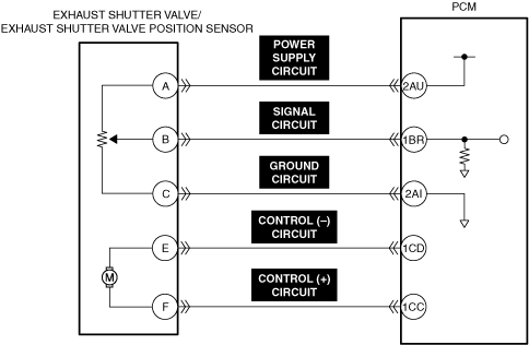
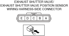
•  Exhaust shutter valve/exhaust shutter valve position sensor connector or terminals malfunction
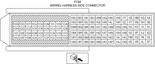
•  PCM connector or terminals malfunction
•  Short to ground in any of the following exhaust shutter valve/exhaust shutter valve position sensor circuits.
―  Signal circuit
―  Control (+) circuit
―  Control (−) circuit
•  Short to power supply in any of the following exhaust shutter valve/exhaust shutter valve position sensor circuits.
―  Signal circuit
―  Control (+) circuit
―  Control (−) circuit
•  Open circuit in any of the following exhaust shutter valve/exhaust shutter valve position sensor circuits.
―  Signal circuit
―  Control (+) circuit
―  Control (−) circuit
•  Exhaust shutter valve malfunction
•  Exhaust shutter valve position sensor malfunction
•  PCM malfunction


Function Explanation (DTC Detection Outline)

•  The internal structure of the exhaust shutter valve is designed so that the valve returns to the fully-open position when the exhaust shutter valve is not energized.
If the speed at which the exhaust shutter valve returns from the closed position to the fully-open position is extremely slow when the exhaust shutter valve energization is turned off, the PCM determines a malfunction in the exhaust shutter valve and stores a DTC.

Repeatability Verification Procedure

1.  Start the engine and leave it idling for 10 min or more.

2.  Switch the ignition off.


PID Item/Simulation Item Used In Diagnosis

PID/DATA monitor item table

PIDs

Reference

EX_SHUT_VLV_ACT


Function Inspection Using M-MDS

Step

Inspection

Results

Action

1
PURPOSE: VERIFY RELATED REPAIR INFORMATION OR SERVICE INFORMATION AVAILABILITY
•  Verify related Service Bulletins, on-line repair information, or Service Information availability.
•  Is any related Information available?
Yes
Perform repair or diagnosis according to the available information.
•  If the vehicle is not repaired, go to the next step.
No
Go to the next step.
2
PURPOSE: RECORD VEHICLE STATUS WHEN DTC WAS DETECTED TO UTILIZE WITH REPEATABILITY VERIFICATION
•  Record the freeze frame data/snapshot data.
Note
•  Recording can be facilitated using the screen capture function of the PC.
Go to Troubleshooting Diagnostic Procedure to perform the procedure from Step 1.
3
PURPOSE: VERIFY CONNECTOR CONNECTIONS
•  Access the following PIDs using the M-MDS:
―  EX_SHUT_VLV_ACT
•  Does the PID value fluctuate when the following connectors are shaken?
―  Exhaust shutter valve/exhaust shutter valve position sensor
―  PCM
Yes
Inspect the related wiring harness and connector.
•  Repair or replace the malfunctioning part.
Go to Troubleshooting Diagnostic Procedure to perform the repair completion verification.
No
Go to Troubleshooting Diagnostic Procedure to perform the procedure from Step 1.


Troubleshooting Diagnostic Procedure

Intention of troubleshooting procedure
•  Step 1—3
―  Inspect the wiring harness between the exhaust shutter valve/exhaust shutter valve position sensor and the PCM.
•  Step 4
―  Perform a unit inspection of the exhaust shutter valve.
•  Step 5
―  Perform a unit inspection of the exhaust shutter valve position sensor.
•  Repair completion verification
―  Verify that the primary malfunction is resolved and there are no other malfunctions.

Step

Inspection

Results

Action

1
INSPECT EXHAUST SHUTTER VALVE/EXHAUST SHUTTER VALVE POSITION SENSOR SIGNAL CIRCUIT AND CONTROL (+) CIRCUIT AND CONTROL (−) CIRCUIT FOR SHORT TO GROUND
•  Inspect the applicable circuit for a short to ground.
•  Is the circuit normal?
Yes
Go to the next step.
No
Repair or replace the malfunctioning location and perform the repair completion verification.
2
INSPECT EXHAUST SHUTTER VALVE/EXHAUST SHUTTER VALVE POSITION SENSOR SIGNAL CIRCUIT AND CONTROL (+) CIRCUIT AND CONTROL (−) CIRCUIT FOR SHORT TO POWER SUPPLY
•  Inspect the applicable circuit for a short to power supply.
•  Is the circuit normal?
Yes
Go to the next step.
No
Repair or replace the malfunctioning location and perform the repair completion verification.
3
INSPECT EXHAUST SHUTTER VALVE/EXHAUST SHUTTER VALVE POSITION SENSOR SIGNAL CIRCUIT AND CONTROL (+) CIRCUIT AND CONTROL (−) CIRCUIT FOR OPEN CIRCUIT
•  Inspect the applicable circuit for open circuit.
•  Is the circuit normal?
Yes
Go to the next step.
No
Repair or replace the malfunctioning location and perform the repair completion verification.
4
PURPOSE: INSPECT EXHAUST SHUTTER VALVE FOR MALFUNCTION
•  Inspect the applicable part.
•  Is the part normal?
Yes
Go to the next step.
No
Repair or replace the malfunctioning location and perform the repair completion verification.
5
INSPECT EXHAUST SHUTTER VALVE POSITION SENSOR FOR MALFUNCTION
•  Is the part normal?
Yes
Go to the next step.
No
Repair or replace the malfunctioning location and perform the repair completion verification.
Repair completion verification 1
PURPOSE: VERIFY THAT VEHICLE IS REPAIRED
•  Install/connect the part removed/disconnected during the troubleshooting procedure.
•  Clear the DTC recorded in the memory.
•  Replicate the vehicle conditions at the time the DTC was detected using the following procedure.
―  Implement the repeatability verification procedure.
•  Perform the DTC inspection for the PCM.
•  Is the same Pending DTC present?
Yes
Refer to the controller area network (CAN) malfunction diagnosis flow to inspect for a CAN communication error.
If the CAN communication is normal, perform the diagnosis from Step 1.
•  If the malfunction recurs, replace the PCM, then go to the next step.
No
Go to the next step.
Repair completion verification 2
PURPOSE: VERIFY IF OTHER DTCs DISPLAYED
•  Perform the DTC inspection.
•  Are any other DTCs displayed?
Yes
Repair the malfunctioning location according to the applicable DTC troubleshooting.
No
DTC troubleshooting completed.