1. : Mazda SST number
2. : Global SST number
1: 49 UN31 0123
2: 310–123
Wrench
FUEL PUMP UNIT REMOVAL/INSTALLATION [SKYACTIV-G (WITHOUT CYLINDER DEACTIVATION (E))]
id0114u1800900
Special Service Tool (SST)
|
1. : Mazda SST number
2. : Global SST number
|
|
|
1: 49 UN31 0123
2: 310–123
Wrench
|
|
Replacement Part
|
Packing
Quantity: 1
Location of use: Fuel pump unit
|
1. Complete the “BEFORE SERVICE PRECAUTION”. (See BEFORE SERVICE PRECAUTION [SKYACTIV-G (WITHOUT CYLINDER DEACTIVATION (E))].)
2. Disconnect the negative battery terminal. (See NEGATIVE BATTERY TERMINAL DISCONNECTION/CONNECTION [(E)].)
3. Remove the rear seat cushion. (See REAR SEAT CUSHION REMOVAL/INSTALLATION.)
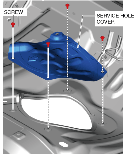
4. Remove the service hole cover.
am3zzw00021182
|
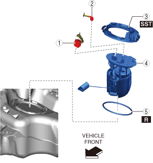
5. Remove in the order indicated in the table.
2WD
ac30zw00003910
|
|
1
|
Fuel pump unit connector
|
|
2
|
Quick release connector
|
|
3
|
Set plate component
|
|
4
|
Fuel pump unit
|
|
5
|
Packing
|
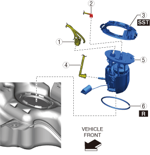
AWD
ac30zw00003911
|
|
1
|
Fuel pump unit connector
|
|
2
|
Quick release connector
|
|
3
|
Set plate component
|
|
4
|
Quick release connector
|
|
5
|
Fuel pump unit
|
|
6
|
Packing
|
6. Install in the reverse order of removal.
7. Complete the “AFTER SERVICE PRECAUTION”. (See AFTER SERVICE PRECAUTION [SKYACTIV-G (WITHOUT CYLINDER DEACTIVATION (E))].)
Set Plate Component Removal Note
1. Install the SST shown in the figure.
am3zzw00021185
|
2. Remove the set plate component using the SST.
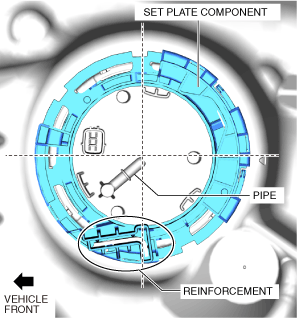
Set Plate Component Installation Note
1. Align the reinforcement part of the set plate component near the pipe area of the fuel pump unit as shown in the figure and assemble.
am3zzw00032849
|