 |
am3zzw00034775
GENERATOR INSPECTION [SKYACTIV-G (WITHOUT CYLINDER DEACTIVATION (E))]
id0117008003v1
Charging System Warning Light
1. Verify that the battery is fully charged. (See BATTERY INSPECTION [(E)].)
2. Verify that the assembly condition of the drive belt is normal. (See DRIVE BELT INSPECTION [SKYACTIV-G (WITHOUT CYLINDER DEACTIVATION (E))].)
3. Switch the ignition ON (engine off), verify that the charging system warning light illuminates.
4. Verify that the charging system warning light turns off after the engine is started.
Generator
Generator voltage inspection
1. Verify that the battery is fully charged. (See BATTERY INSPECTION [(E)].)
2. Verify that the assembly condition of the drive belt is normal. (See DRIVE BELT INSPECTION [SKYACTIV-G (WITHOUT CYLINDER DEACTIVATION (E))].)
3. Turn off all electrical loads.
4. Start the engine.
5. Verify that the generator rotates smoothly without any noise while the engine is running.
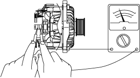
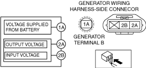
6. Measure the voltage at each terminal using a tester.
am3zzw00034775
|
Generator current inspection
1. Verify that the battery is fully charged. (See BATTERY INSPECTION [(E)].)
2. Verify that the assembly condition of the drive belt is normal. (See DRIVE BELT INSPECTION [SKYACTIV-G (WITHOUT CYLINDER DEACTIVATION (E))].)
3. Disconnect the negative battery terminal. (See NEGATIVE BATTERY TERMINAL DISCONNECTION/CONNECTION [(E)].)
4. Connect a tester, which can read 120 A or more, between generator terminal B and generator terminal B cable.
5. Connect the negative battery terminal. (See NEGATIVE BATTERY TERMINAL DISCONNECTION/CONNECTION [(E)].)
6. Turn off all electrical loads.
7. Start the engine.
8. With the electric loads such as headlights, blower motor, rear window defogger, brake lights turned on, verify that the current increases.
Generator generated current (reference value) [Ambient temperature: 20 °C {68 °F}, Engine hot]
|
Engine speed (rpm) |
Terminal 1A voltage (V) |
Generator output current (A) |
|---|---|---|
|
1,000
|
13
|
83
|
|
1,000
|
15
|
83
|
|
2,000
|
13
|
98
|
|
2,000
|
15
|
105
|
Generator Internal Parts
Rotor
1. Measure the resistance between the slip rings using a ohmmeter.
am3zzw00023991
|
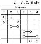
Stator coil
1. Verify that the continuity is as indicated in the table.
am3zzw00023992
|
am6zzw00002353
|
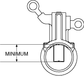
Brush
1. Inspect brushes for wear.
am3zzw00023993
|
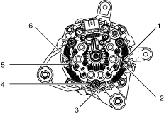
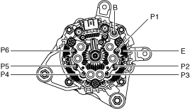
Rectifier (Using an analog circuit tester)
1. Inspect for continuity of the diodes using an analog circuit tester.
am3zzw00023994
|
Specification
|
Positive |
Negative |
Continuity |
|---|---|---|
|
P1, P2, P3, P4, P5, P6
|
B
|
Yes
|
|
B
|
P1, P2, P3, P4, P5, P6
|
No
|
2. Inspect for continuity of the diodes using an analog circuit tester.
Specification
|
Positive |
Negative |
Continuity |
|---|---|---|
|
E
|
P1, P2, P3, P4, P5, P6
|
Yes
|
|
P1, P2, P3, P4, P5, P6
|
E
|
No
|
Rectifier (Using a digital circuit tester)
1. Inspect for continuity of the diodes using a digital circuit tester.
Specification
|
Positive |
Negative |
Continuity |
|---|---|---|
|
P1, P2, P3, P4, P5, P6
|
B
|
No
|
|
B
|
P1, P2, P3, P4, P5, P6
|
Yes
|
2. Inspect for continuity of the diodes using a digital circuit tester.
Specification
|
Positive |
Negative |
Continuity |
|---|---|---|
|
E
|
P1, P2, P3, P4, P5, P6
|
No
|
|
P1, P2, P3, P4, P5, P6
|
E
|
Yes
|