|
1
|
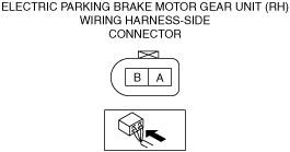
INSPECT ELECTRIC PARKING BRAKE MOTOR GEAR UNIT (RH) CONNECTOR FOR MALFUNCTION
• Inspect the applicable connector and terminal.
• Are the connector and terminal normal?
|
Yes
|
Go to the next step.
|
|
No
|
Repair or replace the malfunctioning location and perform the repair completion verification.
|
|
2
|
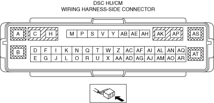
INSPECT DSC HU/CM CONNECTOR FOR MALFUNCTION
• Inspect the applicable connector and terminal.
• Are the connector and terminal normal?
|
Yes
|
Go to the next step.
|
|
No
|
Repair or replace the malfunctioning location and perform the repair completion verification.
|
|
3
|
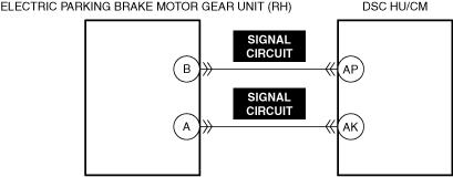
INSPECT ELECTRIC PARKING BRAKE MOTOR GEAR UNIT (RH) SIGNAL CIRCUIT FOR OPEN CIRCUIT
• Inspect the applicable circuit for open circuit.
• Is the circuit normal?
|
Yes
|
Go to the next step.
|
|
No
|
Repair or replace the malfunctioning location and perform the repair completion verification.
|
|
4
|
INSPECT ELECTRIC PARKING BRAKE MOTOR GEAR UNIT (RH) FOR MALFUNCTION DEPENDING ON REPEATABILITY
• Install/connect the part removed/disconnected during the troubleshooting procedure.
• Clear the DTC recorded in the memory.
• Perform the following procedure 3 times or more.
-
― Pull up the electric parking brake switch to operate the electric parking brake.
― Press down the electric parking brake switch to release the electric parking brake.
• Perform the DTC inspection for the DSC HU/CM.
• Is the same Pending DTC present?
|
Yes
|
Refer to the controller area network (CAN) malfunction diagnosis flow to inspect for a CAN communication error.
If the CAN communication is normal, replace the malfunctioning location and perform the repair completion verification.
|
|
No
|
Go to repair completion verification 2.
|
|
Repair completion verification 1
|
VERIFY THAT VEHICLE IS REPAIRED
• Install/connect the part removed/disconnected during the troubleshooting procedure.
• Clear the DTC recorded in the memory.
• Perform the following procedure 3 times or more.
-
― Pull up the electric parking brake switch to operate the electric parking brake.
― Press down the electric parking brake switch to release the electric parking brake.
• Perform the DTC inspection for the DSC HU/CM.
• Is the same Pending DTC present?
|
Yes
|
Refer to the controller area network (CAN) malfunction diagnosis flow to inspect for a CAN communication error.
If the CAN communication is normal, perform the diagnosis from Step 1.
• If the malfunction recurs, replace the DSC HU/CM, then go to the next step.
|
|
No
|
Go to the next step.
|
|
Repair completion verification 2
|
VERIFY IF OTHER DTCs DISPLAYED
• Perform the DTC inspection.
• Are any DTCs displayed?
|
Yes
|
Repair the malfunctioning location according to the applicable DTC troubleshooting.
|
|
No
|
DTC troubleshooting completed.
|