• When replacing the DSC HU/CM, perform the configuration to assure that the system operates correctly. (See CONFIGURATION.)
• The internal parts of the DSC HU/CM could be damaged if dropped. Be careful not to drop the DSC HU/CM. Replace the DSC HU/CM if it is subjected to an impact.
• Brake fluid will damage painted surfaces. Be careful not to spill any on painted surfaces. In addition, if there is any brake fluid on the wiring harness, the wire insulation may corrode causing a malfunction such as a short circuit. If brake fluid gets on a painted surface or wiring harness, wash and flush it off completely with water immediately.
Note
• After replacing the DSC HU/CM and performing an operation/release of the electric parking brake, the DSC HU/CM performs a check of the related parts, and records the operation/release condition of the electric parking brake.
• Tighten the brake pipe flare nut using any commercially available flare nut wrench.
1. To replace the DSC HU/CM, perform the following procedure.
(1) Connect the M-MDS to the DLC-2.
(2) Switch the ignition ON (engine off).
(3) Activate the M-MDS and perform the following procedure.
1) Press [Start] to start the vehicle identification.
2) Press the [Toolbox] tab.
3) Press the [Work Support] icon.
4) Press [Configuration].
5) Press [Run] to perform the configuration.
6) Press [DSC].
7) When [Install the new ECU] is displayed, move to the DSC HU/CM replacement procedure.
(10) Operate the electric parking brake switch using the following procedure to verify the operation of the electric parking brake and perform the automatic adjustment.
1) Switch the ignition ON (engine off).
2) Operate the electric parking brake.
• If the electric parking brake cannot be operated, release it once and then try to re-operate it.
― If the electric parking brake cannot be operated/released, perform a DTC inspection as a malfunction of the electric parking brake may have occurred. (See DTC INSPECTION.)
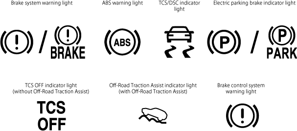
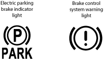
3) Verify that the electric parking brake indicator light turns on and the brake control system warning light turns off.
ac30zw00003451
• If the electric parking brake indicator light does not turn on, the electric parking brake indicator light flashes, or the brake control system warning light does not turn off, perform a DTC inspection as a malfunction of the electric parking brake may have occurred. (See DTC INSPECTION.)
4) Release the electric parking brake.
5) Verify that the electric parking brake indicator light and the brake control system warning light turn off.
• If the electric parking brake indicator light and the brake control system warning light do not turn off, perform a DTC inspection as a malfunction of the electric parking brake may have occurred. (See DTC INSPECTION.)
• If sand or other particles get into the connector, it may be difficult to remove. To prevent damaging the connector, be careful not to use excessive force when disconnecting it.
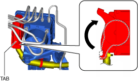
1. Pull the lock lever up in the direction of the arrow while pressing the tab of the lock lever.
am3zzw00034294
2. Disconnect the DSC HU/CM connector.
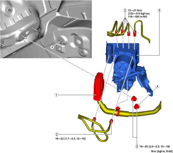
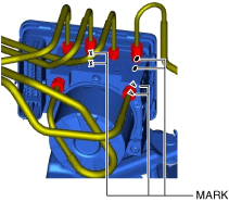
Brake Pipe Removal Note
1. Place an alignment mark on the brake pipe and DSC HU/CM.
am3zzw00029785
2. Apply protective tape to the connector to prevent brake fluid from entering.
3. Disconnect the brake pipes.
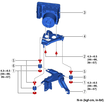
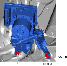
Nuts Installation Note
1. Tighten nut A to the specified torque.
am3zzw00029786
2. Tighten nut B to the specified torque.
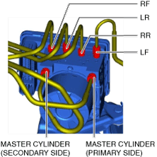
Brake Pipe Installation Note
1. Align the marks made before removal and install the brake pipe to the DSC HU/CM and brake pipe joint referring to the figure.
am3zzw00034295
2. Tighten the brake pipe to the specified torque using the commercially available flare nut wrench.
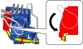
DSC HU/CM Connector Installation Note
1. Connect the connector and pull the lock lever down in the direction of the arrow.
am3zzw00034296
2. After connecting the connector, verify that the connector cover is completely pushed in.
 ac30zw00003451