|
1
|
RECORD VEHICLE STATUS WHEN DTC WAS DETECTED TO UTILIZE WITH REPEATABILITY VERIFICATION
• Record the freeze frame data/snapshot data.
-
Note
-
• Recording can be facilitated using the screen capture of the PC function.
|
—
|
Go to the next step.
|
|
2
|
VERIFY RELATED REPAIR INFORMATION OR SERVICE INFORMATION AVAILABILITY
• Verify related Service Bulletins, on-line repair information, or Service Information availability.
• Is any related information available?
|
Yes
|
Perform repair or diagnosis according to the available information.
• If the vehicle is not repaired, go to the next step.
|
|
No
|
Go to the next step.
|
|
3
|
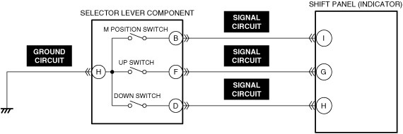
VERIFY BODY CONTROL MODULE (BCM) DTC
• Perform the DTC inspection for the body control module (BCM).
• Is a shift panel (indicator) related DTC displayed?
|
Yes
|
Go to the applicable DTC inspection.
|
|
No
|
Go to the next step.
|
|
4
|
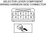
INSPECT SELECTOR LEVER COMPONENT CONNECTOR FOR MALFUNCTION
• Inspect the applicable connector and terminal.
• Are the connector and terminal normal?
|
Yes
|
Go to the next step.
|
|
No
|
Repair or replace the malfunctioning location and perform the repair completion verification.
|
|
5
|
INSPECT SELECTOR LEVER COMPONENT FOR MALFUNCTION
• Inspect the applicable part.
• Is the part normal?
|
Yes
|
Go to the next step.
|
|
No
|
Repair or replace the malfunctioning location and perform the repair completion verification.
|
|
6
|
INSPECT SELECTOR LEVER COMPONENT GROUND CIRCUIT FOR OPEN CIRCUIT
• Inspect the applicable circuit for open circuit.
• Is the circuit normal?
|
Yes
|
Go to the next step.
|
|
No
|
Repair or replace the malfunctioning location and perform the repair completion verification.
|
|
7
|
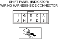
INSPECT SHIFT PANEL (INDICATOR) CONNECTOR FOR MALFUNCTION
• Inspect the applicable connector and terminal.
• Are the connector and terminal normal?
|
Yes
|
Go to the next step.
|
|
No
|
Repair or replace the malfunctioning location and perform the repair completion verification.
|
|
8
|
INSPECT SELECTOR LEVER COMPONENT SIGNAL CIRCUIT FOR SHORT TO GROUND
• Inspect the applicable circuit for a short to ground.
• Is the circuit normal?
|
Yes
|
Go to the next step.
|
|
No
|
Repair or replace the malfunctioning location and perform the repair completion verification.
|
|
9
|
INSPECT SELECTOR LEVER COMPONENT SIGNAL CIRCUIT FOR SHORT TO POWER SUPPLY
• Inspect the applicable circuit for a short to power supply.
• Is the circuit normal?
|
Yes
|
Go to the next step.
|
|
No
|
Repair or replace the malfunctioning location and perform the repair completion verification.
|
|
10
|
INSPECT SELECTOR LEVER COMPONENT SIGNAL CIRCUIT FOR OPEN CIRCUIT
• Inspect the applicable circuit for open circuit.
• Is the circuit normal?
|
Yes
|
Replace the shift panel (indicator) and perform the repair completion verification.
|
|
No
|
Repair or replace the malfunctioning location and perform the repair completion verification.
|
|
Repair completion verification
|
VERIFY DTC TROUBLESHOOTING COMPLETED
• Install/connect the part removed/disconnected during the troubleshooting procedure.
• Clear the DTC using the M-MDS.
• Perform the following procedure to ensure that the DTC has been resolved:
-
1. Verify that the battery voltage is 8 V or more.
2. Drive the vehicle for 1 s or more under the following condition:
-
• Selector lever position: Except D position
3. Drive the vehicle for 1 s or more under the following conditions:
-
• Selector lever position: D position
• Up switch: On
4. Drive the vehicle for 1 s or more under the following conditions:
-
• Selector lever position: D position
• Down switch: On
• Perform the DTC inspection using the M-MDS.
• Are any DTCs present?
|
Yes
|
Repair the malfunctioning location according to the applicable DTC troubleshooting.
|
|
No
|
DTC troubleshooting completed.
|