 |
am3zzw00026471
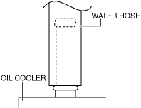
OIL COOLER REMOVAL/INSTALLATION [ET6A-EL, ET6AX-EL (SKYACTIV-D 1.8)]
id0517n31175o8
Replacement Part
|
O-ring
Quantity: 2
Location of use: Oil cooler
|
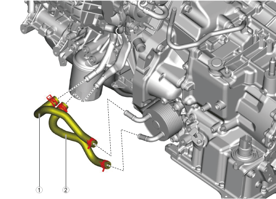
Water Hose
1. Remove the front under cover No.2. (See FRONT UNDER COVER No.2 REMOVAL/INSTALLATION.)
2. Drain the engine coolant. (See ENGINE COOLANT REPLACEMENT [SKYACTIV-D 1.8].)
3. Remove in the order indicated in the table.
4. Install in the reverse order of removal.
5. Add the engine coolant. (See ENGINE COOLANT REPLACEMENT [SKYACTIV-D 1.8].)
am3zzw00026471
|
|
1
|
Water hose No.1
|
|
2
|
Water hose No.2
|
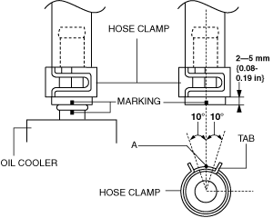
Water hose No.1 and No.2 (oil cooler side) installation note
1. Install the water hose to the oil cooler as shown in the figure with the hose clamp expanded.
am3uuw00008323
|
2. Install the hose clamp so that center A of the hose clamp tab is within the range shown in the figure.
ac30zw00003800
|
3. Verify that the hose clamp does not interfere with any other components.
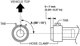
Water hose No.1 (water pipe side) installation note
1. Install the water hose No.1 to the water pipe as shown in the figure with the hose clamp expanded.
am2zzw00009476
|
2. The hose clamp installation direction is within range A shown in the figure.
ac30zw00003801
|
3. Verify that the hose clamp does not interfere with any other components.
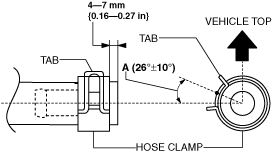
Water hose No.2 (water pipe side) installation note
1. Install the water hose No.2 to the water pipe as shown in the figure with the hose clamp expanded.
am2zzw00009476
|
2. The hose clamp installation direction is within range A shown in the figure.
ac30zw00003802
|
3. Verify that the hose clamp does not interfere with any other components.
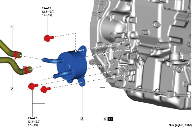
Oil Cooler
1. Disconnect the negative battery terminal. (See NEGATIVE BATTERY TERMINAL DISCONNECTION/CONNECTION [(E)].)
2. Remove the front under cover No.2. (See FRONT UNDER COVER No.2 REMOVAL/INSTALLATION.)
3. Drain the ATF. (See AUTOMATIC TRANSAXLE FLUID (ATF) REPLACEMENT [ET6A-EL, ET6AX-EL (E)].)
4. Drain the engine coolant. (See ENGINE COOLANT REPLACEMENT [SKYACTIV-D 1.8].)
5. Remove in the order indicated in the table.
6. Install in the reverse order of removal.
7. Add the engine coolant. (See ENGINE COOLANT REPLACEMENT [SKYACTIV-D 1.8].)
8. Add the ATF. (See AUTOMATIC TRANSAXLE FLUID (ATF) REPLACEMENT [ET6A-EL, ET6AX-EL (E)].)
9. Perform the “Mechanical System Test”. (See MECHANICAL SYSTEM TEST [ET6A-EL, ET6AX-EL (E)].)
am3zzw00026472
|
|
1
|
Water hose No.1
|
|
2
|
Water hose No.2
|
|
3
|
Water-cooled oil cooler
|
|
4
|
O-ring
|
Water hose No.1 and No.2 (oil cooler side) installation note
1. Install the water hose to the oil cooler as shown in the figure with the hose clamp expanded.
am3uuw00008323
|
2. Install the hose clamp so that center A of the hose clamp tab is within the range shown in the figure.
ac30zw00003803
|
3. Verify that the hose clamp does not interfere with any other components.