49 JP02 001
Adjustable wrench

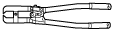
49 T025 001
Boot clamp crimpers
STEERING GEAR AND LINKAGE ASSEMBLY [(E)]
id0613008021x2
Special service tool (SST)
|
49 JP02 001
Adjustable wrench
|
|
49 T025 001
Boot clamp crimpers
|
|
Replacement part
|
Boot band
Quantity: 2
Location of use: Boot
|
Oil and chemical type
|
Grease
Type: Molywhite
|
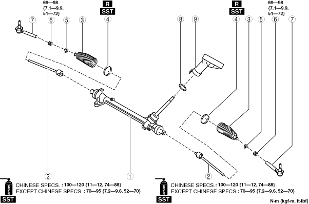
1. Assemble in the order shown in the figure.
2. Install the steering gear and linkage to the front crossmember component. (See STEERING GEAR AND LINKAGE REMOVAL/INSTALLATION [(E)].)
ac30zw00004442
|
|
1
|
Steering gear
|
|
2
|
Tie rod
(See Tie Rod Assembly Note.)
|
|
3
|
Boot
|
|
4
|
Boot band
(See Boot Band Assembly Note.)
|
|
5
|
Boot clamp
|
|
6
|
Locknut
|
|
7
|
Tie-rod end
(See Tie-rod End Assembly Note.)
|
|
8
|
O-ring
|
|
9
|
Dust cover
(See Dust Cover Assembly Note.)
|
Tie Rod Assembly Note
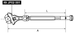
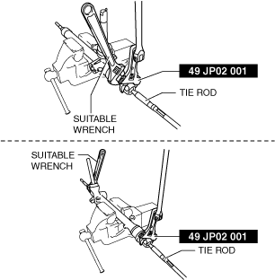
1. Install the SST to the torque wrench as shown in the figure, set it on the tie rod, and then measure dimensions A and L shown in the figure.
adejjw00015170
|
2. Tighten the tie rod using the SST after calculating the tightening torque using the following formula.
am3zzw00033063
|
Boot Band Assembly Note
1. Assemble the boot band to the boot.
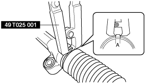
2. Crimp the boot band using the SST.
ac5jjw00002709
|
3. Verify that crimp A of the boot band is within the standard.
4. Rotate the boot by hand and verify that the boot is securely installed by the boot band.
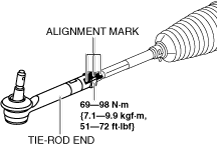
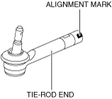
Tie-rod End Assembly Note
1. Align the marks that were made before removing the tie-rod end, and assemble the tie-rod end to the tie rod.
ac30zw00001998
|
ac30zw00001999
|
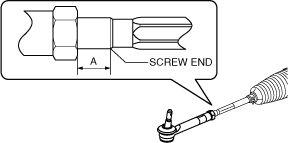
2. Verify that dimension A shown in the figure is within the standard.
ac30zw00000553
|
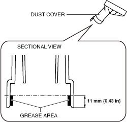
Dust Cover Assembly Note
1. Apply grease to the inside of the dust cover.
ac30zw00002000
|
2. Assemble the dust cover to the steering gear.
3. Verify that the dust cover does not rotate.