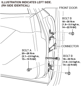
• Removing the front door without supporting it could cause the front door to fall and cause serious injury. Always perform the procedure with at least one other person to prevent the front door from falling.
Caution
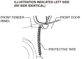
• When the front door checker securing bolt is removed, the front door may open until it contacts the front fender panel causing the front door and the front fender panel to be damaged. Before removing the front door, overlap and adhere the protective tape to the position shown in the figure and be careful not to damage the front door and the front fender panel.
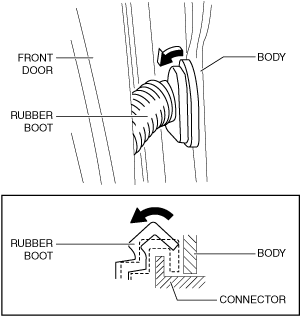
1. Partially peel back the rubber boot in the direction of the arrow shown in the figure and remove it from the connector.
am3zzw00029690
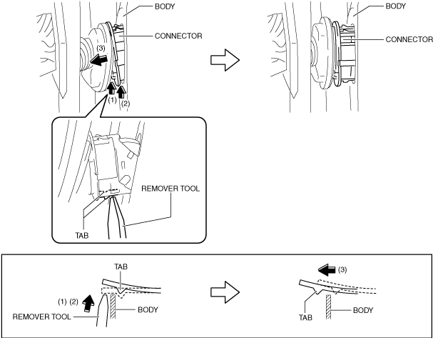
2. Using a remover tool, press the tabs in the direction of arrows (1) and (2) shown in the figure and remove the connector from the body in the direction of arrow (3).
am3zzw00029691
3. Using a remover tool, press the tabs in the direction of arrows (1) and (2) shown in the figure and remove the upper part of the connector from the body in the direction of arrow (3).
am3zzw00029692
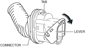
4. Release the lever lock by pressing the connector tab shown in the figure and tilt the lever in the direction of the arrow.