 |
ac30zw00002428
DETERMINING SHORT TO POWER SUPPLY LOCATION (CAN-BUS No.8) [(E)]
id1002x2004700
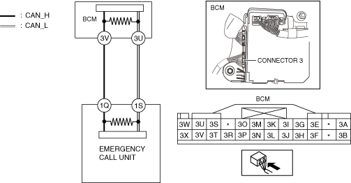
System Wiring Diagram
ac30zw00002428
|
Determination Procedure
|
Step |
Inspection |
Action |
|
|---|---|---|---|
|
1
|
INSPECT CAN LINE BETWEEN BODY CONTROL MODULE (BCM) AND emergency call unit FOR SHORT TO POWER SUPPLY
• Switch the ignition off.
• Disconnect the negative battery terminal.
• Disconnect the connector 3 which has body control module (BCM) terminals 3V and 3U.
• Connect the negative battery terminal.
• Switch the ignition ON (engine off).
• Measure the voltage at body control module (BCM) terminals 3V and 3U (wiring harness side).
• Is the voltage between 1.5—3.5 V?
|
Yes
|
Replace the body control module (BCM) because there is a short to the power supply in the body control module (BCM).
|
|
No
|
Go to the next step.
|
||
|
2
|
INSPECT EMERGENCY CALL UNIT FOR SHORT TO POWER SUPPLY
• Switch the ignition off.
• Disconnect the negative battery terminal.
• Disconnect the emergency call unit connector.
• Connect the connector 3 which has body control module (BCM) terminals 3V and 3U.
• Connect the negative battery terminal.
• Switch the ignition ON (engine off).
• Measure the voltage at body control module (BCM) terminals 3V and 3U.
• Is the voltage between 1.5—3.5 V?
|
Yes
|
Replace the emergency call unit because there is a short to the power supply in the emergency call unit.
|
|
No
|
Repair or replace the wiring harness between the emergency call unit and body control module (BCM) because the wiring harness is shorted to the power supply.
|
||