 |
ac30zw00005110
EMERGENCY CALL UNIT REMOVAL/INSTALLATION
id092200669000
L.H.D.
1. Disconnect the negative battery terminal. (See NEGATIVE BATTERY TERMINAL DISCONNECTION/CONNECTION [(E)].)
2. Remove the following parts:
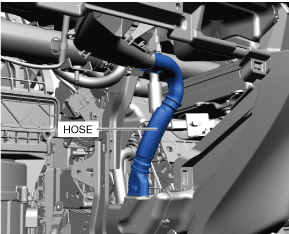
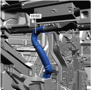
3. Remove the hose.
ac30zw00005110
|
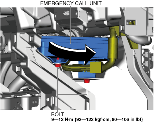
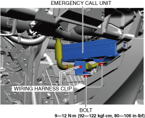
4. Remove the bolts.
ac30zw00005130
|
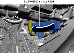
5. Move the emergency call unit in the direction of the arrow shown in the figure.
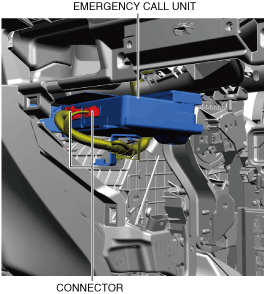
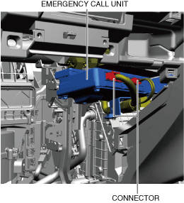
6. Disconnect the connectors.
ac30zw00005131
|
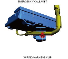
7. Remove the wiring harness clip.
ac30zw00005143
|
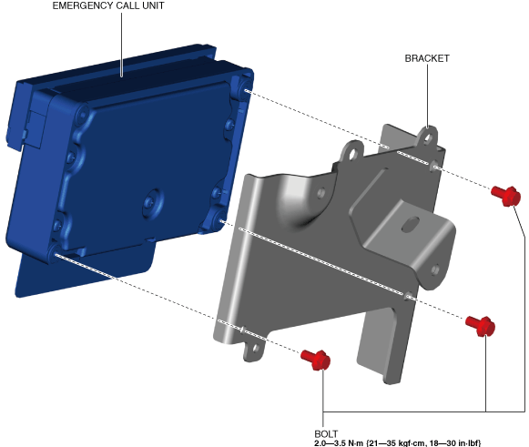
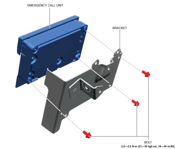
8. Remove the emergency call unit and the bracket as a single unit.
9. Remove the bolts.
ac30zw00003093
|
10. Remove the emergency call unit.
11. Install in the reverse order of removal. (See Emergency Call Unit Installation Note.)
12. If the emergency call unit is replaced, perform the following procedure.
R.H.D.
1. Disconnect the negative battery terminal. (See NEGATIVE BATTERY TERMINAL DISCONNECTION/CONNECTION [(E)].)
2. Remove the following parts:
3. Remove the hose.
ac30zw00005145
|
4. Remove the wiring harness clip.
ac30zw00005146
|
5. Remove the bolts.
6. Move the emergency call unit in the direction of the arrow shown in the figure.
ac30zw00005147
|
7. Disconnect the connectors.
ac30zw00005149
|
8. Remove the emergency call unit and the bracket as a single unit.
9. Remove the bolts.
ac30zw00005148
|
10. Remove the emergency call unit.
11. Install in the reverse order of removal. (See Emergency Call Unit Installation Note.)
12. If the emergency call unit is replaced, perform the following procedure.
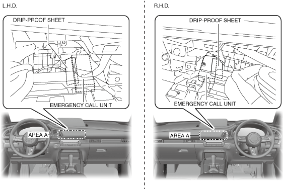
Emergency Call Unit Installation Note
1. Verify from area A that the drip-proof sheet of the emergency call unit is not everted.
ac30zw00005144
|
2. If the drip-proof sheet is everted, fix it so that it is not everted as shown in the figure.