|
1
|
INSPECT VEHICLE CONTROL MODULE (VCM) AND BODY CONTROL MODULE (BCM) FOR MALFUNCTION
• Switch the ignition OFF, and then switch it ON (engine off).
• Perform the DTC inspection for the vehicle control module (VCM) and the body control module (BCM).
• Is a DTC related to an internal malfunction displayed?
|
Yes
|
Repair the malfunctioning location according to the applicable DTC troubleshooting.
|
|
No
|
Go to the next step.
|
|
2
|
VERIFY REPEATABILITY
• Switch the ignition ON (engine off or on).
• Because a CAN communication is in sleep mode, perform the following operation.
-
― Switch the ignition OFF.
― Remove all of the remote transmitters from the vehicle, lock all doors, and then wait for 10 min.
• Switch the ignition ON (engine off or on).
• Clear the DTC recorded in the memory.
• Switch the ignition OFF, and then switch it ON (engine off or on) and wait for 30 s or more.
• Perform the DTC inspection for the vehicle control module (VCM).
• Is the same Pending DTC present?
|
Yes
|
Go to the next step.
|
|
No
|
Go to repair completion verification 2.
|
|
3
|
INSPECT VEHICLE CONTROL MODULE (VCM) POWER SUPPLY FOR MALFUNCTION
• Perform the DTC inspection for the vehicle control module (VCM).
• Are any of the following DTCs displayed?
-
― U3003:16
― U3003:17
|
Yes
|
Repair the malfunctioning location according to the applicable DTC troubleshooting.
|
|
No
|
Go to the next step.
|
|
4
|
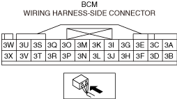
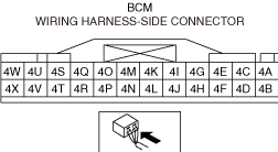
INSPECT BODY CONTROL MODULE (BCM) CONNECTOR FOR MALFUNCTION
• Inspect the following connectors and terminals.
-
― Body control module (BCM) (terminal 3A—3X) (with forward sensing camera (FSC) or driver monitoring (DM))
― Body control module (BCM) (terminal 4A—4X)
• Are the connector and terminal normal?
|
Yes
|
Go to the next step.
|
|
No
|
Repair or replace the malfunctioning location and perform the repair completion verification.
|
|
5
|
DETERMINE MALFUNCTIONING LOCATION
• Connect the negative battery terminal.
• Measure the voltage at the following terminals (part side).
-
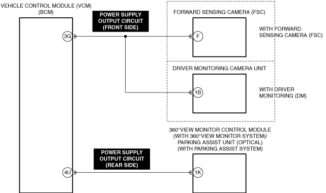
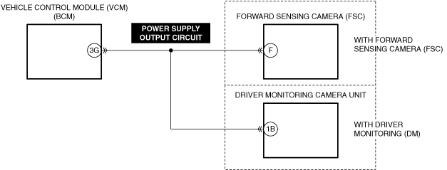
― Body control module (BCM) terminal 3G (with forward sensing camera (FSC) or driver monitoring (DM))
-
― Body control module (BCM) terminal 4U
• Is the voltage normal?
|
Yes
|
Go to the next step.
|
|
No
|
Replace the body control module (BCM) and perform the repair completion verification.
|
|
6
|
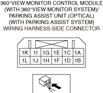
INSPECT 360°VIEW MONITOR CONTROL MODULE (WITH 360°VIEW MONITOR SYSTEM)/PARKING ASSIST UNIT (OPTICAL) (WITH PARKING ASSIST SYSTEM) CONNECTOR FOR MALFUNCTION
• Inspect the applicable connector and terminal.
• Are the connector and terminal normal?
|
Yes
|
Go to the next step.
|
|
No
|
Repair or replace the malfunctioning location and perform the repair completion verification.
|
|
7
|
INSPECT POWER SUPPLY OUTPUT CIRCUIT (REAR SIDE) FOR SHORT TO GROUND
• Inspect the applicable circuit for a short to ground.
• Is the circuit normal?
|
Yes
|
Go to the next step.
|
|
No
|
Repair or replace the malfunctioning location and perform the repair completion verification.
|
|
8
|
INSPECT POWER SUPPLY OUTPUT CIRCUIT (REAR SIDE) FOR SHORT TO POWER SUPPLY
• Inspect the applicable circuit for a short to power supply.
• Is the circuit normal?
|
Yes
|
Go to the next step.
|
|
No
|
Repair or replace the malfunctioning location and perform the repair completion verification.
|
|
9
|
INSPECT POWER SUPPLY OUTPUT CIRCUIT (REAR SIDE) FOR OPEN CIRCUIT
• Inspect the applicable circuit for an open circuit.
• Is the circuit normal?
|
Yes
|
With forward sensing camera (FSC):
• Go to the next step.
Without forward sensing camera (FSC) and with driver monitoring (DM):
• Go to Step 11.
Without forward sensing camera (FSC) and driver monitoring (DM):
• Go to Step 15.
|
|
No
|
Repair or replace the malfunctioning location and perform the repair completion verification.
|
|
10
|
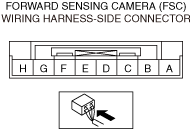
INSPECT FORWARD SENSING CAMERA (FSC) CONNECTOR FOR MALFUNCTION
• Inspect the applicable connector and terminal.
• Are the connector and terminal normal?
|
Yes
|
With driver monitoring (DM):
• Go to the next step.
Without driver monitoring (DM):
• Go to Step 12.
|
|
No
|
Repair or replace the malfunctioning location and perform the repair completion verification.
|
|
11
|
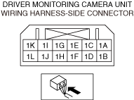
INSPECT DRIVER MONITORING CAMERA UNIT CONNECTOR FOR MALFUNCTION
• Inspect the applicable connector and terminal.
• Are the connector and terminal normal?
|
Yes
|
Go to the next step.
|
|
No
|
Repair or replace the malfunctioning location and perform the repair completion verification.
|
|
12
|
INSPECT POWER SUPPLY OUTPUT CIRCUIT (FRONT SIDE) FOR SHORT TO GROUND
• Inspect the applicable circuit for a short to ground.
• Is the circuit normal?
|
Yes
|
Go to the next step.
|
|
No
|
Repair or replace the malfunctioning location and perform the repair completion verification.
|
|
13
|
INSPECT POWER SUPPLY OUTPUT CIRCUIT (FRONT SIDE) FOR SHORT TO POWER SUPPLY
• Inspect the applicable circuit for a short to power supply.
• Is the circuit normal?
|
Yes
|
Go to the next step.
|
|
No
|
Repair or replace the malfunctioning location and perform the repair completion verification.
|
|
14
|
INSPECT POWER SUPPLY OUTPUT CIRCUIT (FRONT SIDE) FOR OPEN CIRCUIT
• Inspect the applicable circuit for an open circuit.
• Is the circuit normal?
|
Yes
|
Go to the next step.
|
|
No
|
Repair or replace the malfunctioning location and perform the repair completion verification.
|
|
15
|
VERIFY IF MALFUNCTION CAUSE IS 360°VIEW MONITOR CONTROL MODULE (WITH 360°VIEW MONITOR SYSTEM)/PARKING ASSIST UNIT (OPTICAL) (WITH PARKING ASSIST SYSTEM)
• Connect the following connectors.
-
― Body control module (BCM)
― 360°view monitor control module (with 360°view monitor system)/Parking assist unit (optical) (with parking assist system)
• Disconnect the following connectors.
-
― Forward sensing camera (FSC) (with forward sensing camera (FSC))
― Driver monitoring camera unit (with driver monitoring (DM))
• Clear the DTC recorded in the memory.
• Perform the DTC inspection for the vehicle control module (VCM).
• Is the same Pending DTC present?
|
Yes
|
Malfunction cause may be due to 360°view monitor control module (with 360°view monitor system)/parking assist unit (optical) (with parking assist system).
With forward sensing camera (FSC):
• Go to the next step.
Without forward sensing camera (FSC) and with driver monitoring (DM):
• Go to Step 17.
Without forward sensing camera (FSC) and driver monitoring (DM):
• Go to Step 18.
|
|
No
|
360°view monitor control module (with 360°view monitor system)/parking assist unit (optical) (with parking assist system) is normal.
With forward sensing camera (FSC):
• Go to the next step.
Without forward sensing camera (FSC) and with driver monitoring (DM):
• Go to Step 17.
Without forward sensing camera (FSC) and driver monitoring (DM):
• Go to Step 18.
|
|
16
|
VERIFY IF MALFUNCTION CAUSE IS FORWARD SENSING CAMERA (FSC)
• Connect the following connectors.
-
― Body control module (BCM)
― Forward sensing camera (FSC)
• Disconnect the following connectors.
-
― 360°view monitor control module (with 360°view monitor system)/Parking assist unit (optical) (with parking assist system)
― Driver monitoring camera unit (with driver monitoring (DM))
• Clear the DTC recorded in the memory.
• Perform the DTC inspection for the vehicle control module (VCM).
• Is the same Pending DTC present?
|
Yes
|
Malfunction cause may be due to forward sensing camera (FSC).
With driver monitoring (DM):
• Go to the next step.
Without driver monitoring (DM):
• Go to Step 18.
|
|
No
|
Forward sensing camera (FSC) is normal.
With driver monitoring (DM):
• Go to the next step.
Without driver monitoring (DM):
• Go to Step 18.
|
|
17
|
VERIFY IF MALFUNCTION CAUSE IS DRIVER MONITORING CAMERA UNIT
• Connect the following connectors.
-
― Body control module (BCM)
― Driver monitoring camera unit
• Disconnect the following connectors.
-
― 360°view monitor control module (with 360°view monitor system)/Parking assist unit (optical) (with parking assist system)
― Forward sensing camera (FSC) (with forward sensing camera (FSC))
• Clear the DTC recorded in the memory.
• Perform the DTC inspection for the vehicle control module (VCM).
• Is the same Pending DTC present?
|
Yes
|
Malfunction cause may be due to driver monitoring camera unit.
• Go to the next step.
|
|
No
|
Driver monitoring camera unit is normal.
• Go to the next step.
|
|
18
|
IDENTIFY MALFUNCTIONING MODULE
• Verify the number of times DTC U3000:1C is displayed in Steps 15 to 17.
• Is DTC U3000:1C displayed in all steps from Steps 15 to 17?
|
Yes
|
Without forward sensing camera (FSC) and driver monitoring (DM):
• Replace the 360°view monitor control module (with 360°view monitor system)/parking assist unit (optical) (with parking assist system) and perform the repair completion verification.
With forward sensing camera (FSC) or driver monitoring (DM):
• Perform the repair completion verification.
|
|
No
|
Replace the module connected the connector when the DTC is displayed, and perform the repair completion verification.
|
|
Repair completion verification 1
|
VERIFY THAT VEHICLE IS REPAIRED
• Install/connect the part removed/disconnected during the troubleshooting procedure.
• Clear the DTC recorded in the memory.
• Perform the DTC inspection for the vehicle control module (VCM).
• Is the same Pending DTC present?
|
Yes
|
Refer to the controller area network (CAN) malfunction diagnosis flow to inspect for a CAN communication error.
If the CAN communication is normal, perform the diagnosis from Step 1.
• If the malfunction recurs, replace the body control module (BCM), then go to the next step.
|
|
No
|
Perform the [Action for Non-repeatable Malfunction].
If DTC is displayed
• Repeat the diagnosis from Step 1.
If DTC is not displayed
• Go to repair completion verification 2.
|
|
Repair completion verification 2
|
VERIFY IF OTHER DTCs ARE DISPLAYED
• Perform the DTC inspection.
• Is a DTC displayed?
|
Yes
|
Repair the malfunctioning location according to the applicable DTC troubleshooting.
|
|
No
|
DTC troubleshooting completed.
|