|
1
|
VERIFY DRIVER MONITORING CAMERA UNIT DTCs
• Switch the ignition ON (engine off or on) and wait for 120 s or more.
• Perform the DTC inspection for the driver monitoring camera unit.
• Are any DTCs other than DTC U3000:04 displayed?
|
Yes
|
Repair the malfunctioning location according to the applicable DTC troubleshooting.
|
|
No
|
Go to the next step.
|
|
2
|
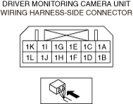
INSPECT DRIVER MONITORING CAMERA UNIT CONNECTOR FOR MALFUNCTION
• Inspect the applicable connector and terminal.
• Are the connector and terminal normal?
|
Yes
|
Go to the next step.
|
|
No
|
Repair or replace the malfunctioning location and perform the repair completion verification procedure.
|
|
3
|
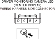
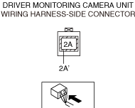
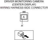
INSPECT CENTER DISPLAY CONNECTOR FOR MALFUNCTION
• Inspect the applicable connector and terminal.
• Are the connector and terminal normal?
|
Yes
|
Go to the next step.
|
|
No
|
Repair or replace the malfunctioning location and perform the repair completion verification procedure.
|
|
4
|
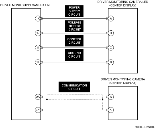
INSPECT DRIVER MONITORING CAMERA COMMUNICATION CIRCUIT FOR SHORT TO GROUND
• Inspect the applicable circuit for a short to ground.
• Is the circuit normal?
|
Yes
|
Go to the next step.
|
|
No
|
Repair or replace the malfunctioning location and perform the repair completion verification procedure.
|
|
5
|
INSPECT DRIVER MONITORING CAMERA LED POWER SUPPLY CIRCUIT, VOLTAGE DETECT CIRCUIT, CONTROL CIRCUIT, AND GROUND CIRCUIT FOR SHORT TO GROUND
• Inspect the applicable circuit for a short to ground.
• Is the circuit normal?
|
Yes
|
Go to the next step.
|
|
No
|
Repair or replace the malfunctioning location and perform the repair completion verification procedure.
|
|
6
|
INSPECT DRIVER MONITORING CAMERA COMMUNICATION CIRCUIT FOR SHORT TO POWER SUPPLY
• Inspect the applicable circuit for a short to power supply.
• Is the circuit normal?
|
Yes
|
Go to the next step.
|
|
No
|
Repair or replace the malfunctioning location and perform the repair completion verification procedure.
|
|
7
|
INSPECT DRIVER MONITORING CAMERA LED POWER SUPPLY CIRCUIT, VOLTAGE DETECT CIRCUIT, CONTROL CIRCUIT, AND GROUND CIRCUIT FOR SHORT TO POWER SUPPLY
• Inspect the applicable circuit for a short to power supply.
• Is the circuit normal?
|
Yes
|
Go to the next step.
|
|
No
|
Repair or replace the malfunctioning location and perform the repair completion verification procedure.
|
|
8
|
INSPECT DRIVER MONITORING CAMERA LED POWER SUPPLY CIRCUIT, VOLTAGE DETECT CIRCUIT, CONTROL CIRCUIT, AND GROUND CIRCUIT FOR SHORT CIRCUIT
• Inspect the applicable circuits for a short circuit.
• Is the circuit normal?
|
Yes
|
Go to the next step.
|
|
No
|
Repair or replace the malfunctioning location and perform the repair completion verification procedure.
|
|
9
|
INSPECT DRIVER MONITORING CAMERA COMMUNICATION CIRCUIT FOR OPEN CIRCUIT
• Inspect the applicable circuit for open circuit.
• Is the circuit normal?
|
Yes
|
Go to the next step.
|
|
No
|
Repair or replace the malfunctioning location and perform the repair completion verification procedure.
|
|
10
|
INSPECT DRIVER MONITORING CAMERA LED POWER SUPPLY CIRCUIT, VOLTAGE DETECT CIRCUIT, CONTROL CIRCUIT, AND GROUND CIRCUIT FOR OPEN CIRCUIT
• Inspect the applicable circuit for open circuit.
• Is the circuit normal?
|
Yes
|
Go to the next step.
|
|
No
|
Repair or replace the malfunctioning location and perform the repair completion verification procedure.
|
|
11
|
INSPECT DRIVER MONITORING CAMERA FOR MALFUNCTION DEPENDING ON REPEATABILITY
• Install/connect the part removed/disconnected during the troubleshooting procedure.
• Clear the DTC recorded in the memory.
• Switch the ignition ON (engine off or on) and wait for 120 s or more.
• Perform the DTC inspection for the driver monitoring camera unit.
• Is the same Pending DTC present?
|
Yes
|
Refer to the controller area network (CAN) malfunction diagnosis flow to inspect for a CAN communication error.
If the CAN communication is normal, replace the center display and perform the repair completion verification.
|
|
No
|
Go to repair completion verification 2.
|
|
Repair completion verification 1
|
VERIFY THAT VEHICLE IS REPAIRED
• Install/connect the part removed/disconnected during the troubleshooting procedure.
• Clear the DTC recorded in the memory.
• Switch the ignition ON (engine off or on) and wait for 120 s or more.
• Perform the DTC inspection for the driver monitoring camera unit.
• Is the same Pending DTC present?
|
Yes
|
Refer to the controller area network (CAN) malfunction diagnosis flow to inspect for a CAN communication error.
If the CAN communication is normal, perform the diagnosis from Step 1.
• If the malfunction recurs, replace the driver monitoring camera unit, then go to the next step.
|
|
No
|
Go to the next step.
|
|
Repair completion verification 2
|
VERIFY IF OTHER DTC IS DISPLAYED
• Perform the DTC inspection.
• Are any other DTCs displayed?
|
Yes
|
Repair the malfunctioning location according to the applicable DTC troubleshooting.
|
|
No
|
DTC troubleshooting completed.
|