Diagnostic procedure
|
STEP
|
INSPECTION
|
ACTION
|
|
|---|---|---|---|
|
1
|
VERIFY FREEZE FRAME DATA AND DIAGNOSTIC MONITORING TEST RESULTS HAS BEEN RECORDED
• Has FREEZE FRAME DATA been recorded?
|
Yes
|
Go to the next step.
|
|
No
|
Record the FREEZE FRAME on the repair order, then go to the next step.
|
||
|
2
|
VERIFY RELATED REPAIR INFORMATION AVAILABILITY
• Verify related Service Information availability.
• Is any related Service Information available?
|
Yes
|
Perform repair or diagnosis according to the available Service information.
If the vehicle is not repaired, go to the next step.
|
|
No
|
Go to the next step.
|
||
|
3
|
INSPECT BATTERY
• Turn the ignition switch off.
• Inspect the battery.
• Is the battery normal?
|
Yes
|
Go to the next step.
|
|
No
|
Replace the battery, then go to Step 7.
|
||
|
4
|
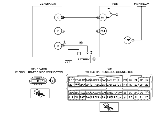
INSPECT POOR INSTALLATION OF GENERATOR TERMINAL
• Turn the ignition switch off.
• Inspect for looseness of generator terminal B installation nut.
• Is nut loose?
|
Yes
|
Tighten generator terminal B installation nut, then go to Step 7.
|
|
No
|
Go to the next step.
|
||
|
5
|
INSPECT POOR INSTALLATION OF BATTERY POSITIVE TERMINAL
• Inspect for looseness of battery positive terminal.
• Is the terminal loose?
|
Yes
|
Connect the battery positive terminal correctly, then go to Step 7.
|
|
No
|
Go to the next step.
|
||
|
6
|
INSPECT BATTERY CHARGING CIRCUIT
• Disconnect the generator terminal B.
• Measure the voltage between generator terminal B (wiring harness-side) and body ground.
• Is the voltage B+?
|
Yes
|
Go to the next step.
|
|
No
|
Repair or replace the wiring harness between generator terminal B and battery positive terminal, then go to the next step.
|
||
|
7
|
VERIFY TROUBLESHOOTING OF DTC P2502 COMPLETED
• Make sure to reconnect all connectors.
• Clear the DTC from the PCM memory using the WDS or equivalent.
• Perform the KOER self-test.
• Is the DTC P2502 present?
|
Yes
|
Replace the PCM, then go to the next step.
|
|
No
|
Go to the next step.
|
||
|
8
|
VERIFY AFTER REPAIR PROCEDURE
• Perform the "AFTER REPAIR PROCEDURE".
• Are any DTCs present?
|
Yes
|
Go to the applicable DTC inspection.
(See DTC TABLE [L8, LF, L3].)
|
|
No
|
Troubleshooting completed.
|
||