Diagnostic procedure
|
STEP
|
INSPECTION
|
ACTION
|
|
|---|---|---|---|
|
1
|
VERIFY FREEZE FRAME DATA AND DIAGNOSTIC MONITORING TEST RESULTS HAS BEEN RECORDED
• Has FREEZE FRAME DATA been recorded?
|
Yes
|
Go to the next step.
|
|
No
|
Record the FREEZE FRAME DATA on the repair order, then go to the next step.
|
||
|
2
|
VERIFY RELATED REPAIR INFORMATION AVAILABILITY
• Verify related Service Information availability.
• Is any related Service Information available?
|
Yes
|
Perform repair or diagnosis according to the available Service information.
If the vehicle is not repaired, go to the next step.
|
|
No
|
Go to the next step.
|
||
|
3
|
VERIFY RELATED PENDING AND STORED DTC
• Turn the ignition switch off, then to the ON position. (Engine off)
• Verify pending and stored DTCs using the WDS or equivalent.
• Is the DTC P2237 or P2251 also present?
|
Yes
|
Go to the appropriate DTC troubleshooting procedures.
|
|
No
|
Go to the next step.
|
||
|
4
|
IDENTIFY TRIGGER DTC FOR FREEZE FRAME DATA
• Is DTC P0134 on the FREEZE FRAME DATA?
|
Yes
|
Go to the next step.
|
|
No
|
Go to troubleshooting procedures for the DTC on the FREEZE FRAME DATA.
(See DTC TABLE [L3 Turbo].)
|
||
|
5
|
VERIFY CURRENT INPUT SIGNAL STATUS
• Warm up the engine.
• Access O2S11 PID using the WDS or equivalent.
• Verify the PID while racing engine in NEUTRAL.
• Is the PID normal?
- -1.0-1.0 A when idle - More than 0.25 mA just after releasing the of accelerator pedal is released (lean condition) |
Yes
|
Go to Step 8.
|
|
No
|
Go to the next step.
|
||
|
6
|
INSPECT INSTALLATION OF A/F SENSOR
• Inspect if the A/F sensor is loosely installed.
• Is the sensor installed securely?
|
Yes
|
Go to the next step.
|
|
No
|
Install the sensor securely, then go to Step 10.
|
||
|
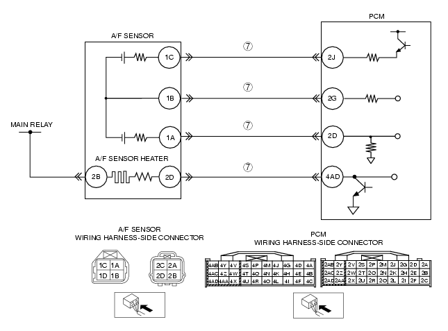
7
|
INSPECT EXHAUST SYSTEM FOR GAS LEAKAGE
• Visually inspect if there is any gas leakage between the exhaust manifold and A/F sensor.
• Is there gas leakage?
|
Yes
|
Repair or replace any malfunctioning exhaust part, then go to Step 10.
|
|
No
|
• Inspect the following wiring harnesses at the wiring harness-side connector terminals for an open circuit, repair or the replace wiring harness if necessary.
• If all the items above are normal, replace the malfunctioning sensor.
Then go to Step 10.
|
||
|
8
|
INSPECT SEALING OF ENGINE COOLANT PASSAGE
• Perform the ENGINE COOLANT LEAKAGE INSPECTION. (See ENGINE COOLANT LEAKAGE INSPECTION [L8, LF, L3, L3 Turbo].)
• Is there any malfunction?
|
Yes
|
Repair or replace the malfunctioning part according to the inspection results, then go to Step 10.
|
|
No
|
Go to the next step.
|
||
|
9
|
INSPECT ENGINE COMPRESSION
• Inspect the engine compression.
• Is it normal?
|
Yes
|
Go to the next step.
|
|
No
|
Perform the engine overhaul for repairs, then go to the next step.
|
||
|
10
|
VERIFY TROUBLESHOOTING OF DTC P0134 COMPLETED
• Make sure to reconnect all disconnected connectors.
• Turn the ignition switch to the ON position. (Engine off)
• Clear the DTC from the memory using the WDS or equivalent.
• Perform the PCM Adaptive Memory Produce Drive Mode and the A/F sensor heater, HO2S heater, A/F sensor, HO2S, and TWC Repair Verification Drive Mode.
(See OBD DRIVE MODE [L3 Turbo].)
• Is the PENDING CODE for this DTC present?
|
Yes
|
Replace the PCM, then go to the next step.
|
|
No
|
Go to the next step.
|
||
|
11
|
VERIFY AFTER REPAIR PROCEDURE
• Perform the "AFTER REPAIR PROCEDURE".
• Are any DTCs present?
|
Yes
|
Go to the applicable DTC troubleshooting.
(See DTC TABLE [L3 Turbo].)
|
|
No
|
Troubleshooting completed.
|
||