|
1
|
VERIFY FREEZE FRAME DATA AND DIAGNOSTIC MONITORING TEST RESULTS HAS BEEN RECORDED
• Has FREEZE FRAME DATA been recorded?
|
Yes
|
Go to the next step.
|
|
No
|
Record the FREEZE FRAME DATA on the repair order, then go to the next step.
|
|
2
|
VERIFY RELATED REPAIR INFORMATION AVAILABILITY
• Verify related Service Information availability.
• Is any related Service Information available?
|
Yes
|
Perform repair or diagnosis according to the available Service information.
If the vehicle is not repaired, go to the next step.
|
|
No
|
Go to the next step.
|
|
3
|
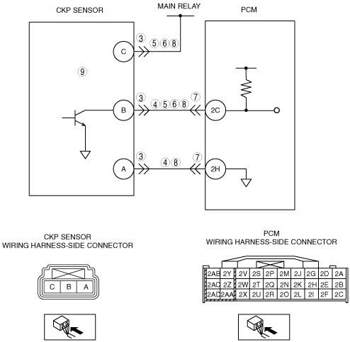
INSPECT CKP SENSOR CONNECTOR FOR POOR CONNECTION
• Verify that the CKP sensor connector is connected securely.
• Is connector normal?
|
Yes
|
Go to the next step.
|
|
No
|
Reconnect the connector, then go to Step 10.
|
|
4
|
INSPECT CKP CIRCUIT FOR SHORT TO POWER SUPPLY
• Turn ignition switch OFF
• Disconnect the CKP sensor connector.
• Turn ignition switch to the ON position (Engine off).
• Measure the voltage between following terminals (harness-side):
-
― CKP sensor terminal A
― CKP sensor terminal B
• Is there any voltage?
|
Yes
|
Repair or replace the suspected wiring harness, then go to Step 10.
|
|
No
|
Go to the next step.
|
|
5
|
INSPECT CKP CIRCUIT FOR SHORT TO GROUND
• Inspect for continuity between following terminal and body ground:
-
― CKP sensor connector terminal C (harness-side)
― CKP sensor connector terminal B (harness-side)
• Is there continuity?
|
Yes
|
Repair or replace the suspected wiring harness, then go to Step 10.
|
|
No
|
Go to the next step.
|
|
6
|
INSPECT CKP CIRCUITS FOR SHORT CIRCUIT
• Inspect for continuity between CKP sensor connector terminals B and C (harness-side).
• Is there continuity?
|
Yes
|
Repair or replace the suspected wiring harness, then go to Step 10.
|
|
No
|
Go to the next step.
|
|
7
|
INSPECT PCM CONNECTOR FOR POOR CONNECTION
• Disconnect the PCM connector.
• Inspect for poor connection (such as damaged/pulled-out pins, corrosion).
• Is there any malfunction?
|
Yes
|
Repair the terminal, then go to Step 10.
|
|
No
|
Go to the next step.
|
|
8
|
INSPECT CKP CIRCUIT FOR OPEN CIRCUIT
• Inspect for continuity between the following circuits:
-
― CKP sensor terminal A (harness-side) and PCM terminal 2H (harness-side)
― CKP sensor terminal B (harness-side) and PCM terminal 2C (harness-side)
― CKP sensor terminal C (harness-side) and main relay
• Are there continuity?
|
Yes
|
Go to the next step.
|
|
No
|
Repair or replace the suspected wiring harness, then go to Step 10.
|
|
9
|
INSPECT CKP SENSOR
• Turn the ignition switch off.
• Perform the CKP sensor inspection.
• Is the CKP sensor normal?
|
Yes
|
Go to the next step.
|
|
No
|
Inspect the CKP sensor pulse wheel for damage. Replace the CKP sensor pulse wheel and go to the next step.
|
|
10
|
VERIFY TROUBLESHOOTING OF DTC P0335 COMPLETED
• Make sure to reconnect all disconnected connectors.
• Turn ignition switch to the ON position (Engine off).
• Clear the DTC from the PCM memory using the WDS or equivalent.
• Start the engine.
• Access the MAF PID using the WDS or equivalent.
-
Note
-
• The MAF PID should indicate 2.0 g/s {0.26 lb/min.} or above during this test
• Is the same DTC present?
|
Yes
|
Replace the PCM, then go to the next step.
|
|
No
|
Go to the next step.
|
|
11
|
VERIFY AFTER REPAIR PROCEDURE
• Perform the “After Repair Procedure”.
• Are any DTCs present?
|
Yes
|
Go to the applicable DTC inspection.
|
|
No
|
Troubleshooting completed.
|