Diagnostic procedure
|
STEP
|
INSPECTION
|
ACTION
|
|
|---|---|---|---|
|
1
|
VERIFY FREEZE FRAME DATA AND DIAGNOSTIC MONITORING TEST RESULTS HAS BEEN RECORDED
• Has FREEZE FRAME DATA been recorded?
|
Yes
|
Go to the next step.
|
|
No
|
Record the FREEZE FRAME DATA on the repair order, then go to the next step.
|
||
|
2
|
VERIFY RELATED REPAIR INFORMATION AVAILABILITY
• Verify related Service Information availability.
• Is any related Service Information available?
|
Yes
|
Perform repair or diagnosis according to the available Service information.
If the vehicle is not repaired, go to the next step.
|
|
No
|
Go to the next step.
|
||
|
3
|
INSPECT DRIVE CHAIN CONDITION
• Verify that the drive chain auto tensioner indicator mark does not exceed limit.
• Is the front drive chain normal?
|
Yes
|
Go to the next step.
|
|
No
|
Replace the and/or adjust drive chain, then go to Step 10.
|
||
|
4
|
INSPECT PCM CONNECTOR FOR POOR CONNECTION
• Turn the ignition switch off.
• Disconnect the PCM connector.
• Inspect for poor connection (damaged, pulled-out terminals, corrosion, etc.).
• Is there any malfunction?
|
Yes
|
Repair the terminals, then go to Step 10.
|
|
No
|
Go to the next step.
|
||
|
5
|
INSPECT GENERATOR CONNECTOR FOR POOR CONNECTION
• Disconnect the generator connector.
• Inspect for poor connection (damaged, pulled-out terminals, corrosion, etc.).
• Is there any malfunction?
|
Yes
|
Repair or replace the terminals, then go to Step 10.
|
|
No
|
Go to the next step.
|
||
|
6
|
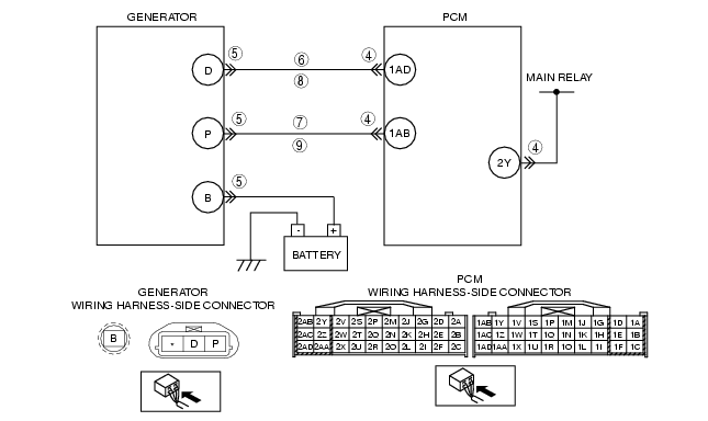
INSPECT GENERATOR CONTROL CIRCUIT FOR SHORT TO GROUND
• Inspect for continuity between generator terminal D (wiring harness-side) and body ground.
• Is there continuity?
|
Yes
|
Repair or replace the wiring harness for a short to ground, then go to Step 10.
|
|
No
|
Go to the next step.
|
||
|
7
|
INSPECT GENERATOR OUTPUT VOLTAGE MONITOR CIRCUIT FOR SHORT TO GROUND
• Inspect for continuity between generator terminal P (wiring harness-side) and body ground.
• Is there continuity?
|
Yes
|
Repair or replace the wiring harness for a short to ground, then go to Step 10.
|
|
No
|
Go to the next step.
|
||
|
8
|
INSPECT GENERATOR CONTROL CIRCUIT FOR OPEN
• Inspect for continuity between generator terminal D (wiring harness-side) and PCM terminal 1AD (wiring harness-side).
• Is there continuity?
|
Yes
|
Go to the next step.
|
|
No
|
Repair or replace the wiring harness for an open circuit, then go to Step 10.
|
||
|
9
|
INSPECT GENERATOR OUTPUT VOLTAGE MONITOR CIRCUIT FOR OPEN CIRCUIT
• Inspect for continuity between generator terminal P (wiring harness-side) and PCM terminal 1AB (wiring harness-side).
• Is there continuity?
|
Yes
|
Repair or replace the generator, then go to the next step.
|
|
No
|
Repair or replace the wiring harness for an open circuit, then go to the next step.
|
||
|
10
|
VERIFY TROUBLESHOOTING OF DTC P2503 COMPLETED
• Make sure to reconnect all connectors.
• Clear the DTC from the PCM memory using the WDS or equivalent.
• Start the engine.
• Is the same DTC present?
|
Yes
|
Replace the PCM, then go to the next step.
|
|
No
|
Go to the next step.
|
||
|
11
|
VERIFY AFTER REPAIR PROCEDURE
• Perform the "AFTER REPAIR PROCEDURE".
• Are any DTCs present?
|
Yes
|
Go to the applicable DTC inspection.
(See DTC TABLE [L3 Turbo].)
|
|
No
|
Troubleshooting completed.
|
||