|
STEP
|
INSPECTION
|
ACTION
|
|
1
|
VERIFY FREEZE FRAME DATA HAS BEEN RECORDED
• Has FREEZE FRAME DATA been recorded?
|
Yes
|
Go to the next step.
|
|
No
|
Record the FREEZE FRAME DATA on the repair order, then go to the next step.
|
|
2
|
VERIFY RELATED REPAIR INFORMATION AVAILABILITY
• Check for related service repair information availability?
|
Yes
|
Perform repair or diagnosis according to the available repair information.
• If the vehicle is not repaired, go to the next step.
|
|
No
|
Go to the next step.
|
|
3
|
IDENTIFY TRIGGER DTC FOR FREEZE FRAME DATA
• Is DTC P0405 on FREEZE FRAME DATA?
|
Yes
|
Go to the next step.
|
|
No
|
Go to troubleshooting procedures for DTC in FREEZE FRAME DATA.
|
|
4
|
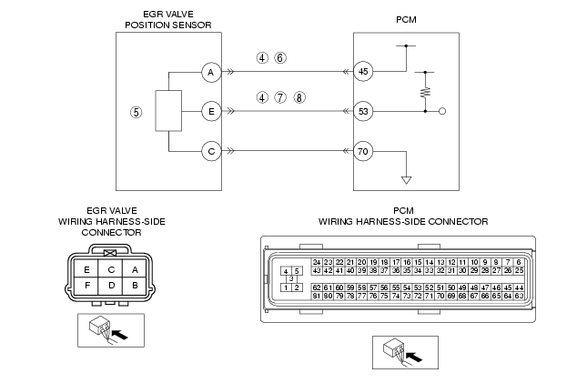
CLASSFY EGR VALVE POSITION SENSOR OR HARNESS MALFUNCTION
• Connect the WDS or equivalent to DLC-2.
• Access EGRP PID V mode.
• Disconnect the EGR valve connector.
• Connect a jumper wire between EGR valve terminal E and A (wiring harness-side).
• Turn the engine switch to the ON position (engine off).
• Is the EGRP PID more than 4.9 V?
|
Yes
|
Go to the next step.
|
|
No
|
Go to Step 6.
|
|
5
|
INSPECT EGR VALVE POSITION SENSOR
• Perform EGR valve position sensor inspection.
• Is the EGR valve position sensor normal?
|
Yes
|
Inspect for poor EGR valve connector terminal A connection.
Repair or replace if necessary, then go to Step 9.
|
|
No
|
Replace the EGR valve, then go to Step 9.
|
|
6
|
INSPECT POWER SUPPLY CIRCUIT VOLTAGE AT EGR VALVE CONNECTOR
• Turn the engine switch to the ON position (engine off).
• Measure voltage at EGR valve terminal A (wiring harness-side).
• Is the voltage within 4.5-5.5 V?
|
Yes
|
Go to the next step.
|
|
No
|
Repair or replace open circuit between EGR valve connector terminal A (wiring harness-side) and PCM connector terminal 45 (wiring harness-side).
Then, go to Step 9.
|
|
7
|
VERIFY EGR POSITION SENSOR SIGNAL CIRCUIT FOR OPEN
• Turn the engine switch off.
• inspect for continuity wiring harness side connectors between EGR valve terminal E and PCM terminal 53.
• Is there any continuity?
|
Yes
|
Go to the next step.
|
|
No
|
Repair or replace for open, then go to Step 9.
|
|
8
|
VERIFY EGR VALVE POSITION SIGNAL CIRCUIT FOR SHORT TO GROUND
• inspect for continuity between EGR valve terminal E (wiring harness-side) and body ground.
• Is there continuity?
|
Yes
|
Repair or replace for short to ground, then go to the next step.
|
|
No
|
Go to the next step.
|
|
9
|
VERIFY TROUBLESHOOTING OF DTC P0405 COMPLETED
• Make sure to reconnect all disconnected connectors.
• Clear the DTC from the PCM memory using the WDS or equivalent.
• Start the engine.
• Is the same DTC present?
|
Yes
|
Replace the PCM, then go to the next step.
|
|
No
|
Go to the next step.
|
|
10
|
VERIFY AFTER REPAIR PROCEDURE
• Perform "AFTER REPAIR PROCEDURE".
• Is any DTCs present?
|
Yes
|
Go to the applicable DTC inspection.
|
|
No
|
Troubleshooting completed.
|