1. Disconnect the negative battery cable.
2. Remove the charge air cooler.
3. Remove the ignition coils. (See IGNITION COIL REMOVAL/INSTALLATION [L8, LF, L3, L3 Turbo].)
4. Remove the spark plugs. (See SPARK PLUG REMOVAL/INSTALLATION [L8, LF, L3, L3 Turbo].)
5. Disconnect the OCV connectors.
6. Disconnect the CMP sensor connector.
7. Disconnect the P/S oil pump connector.
8. Remove the ventilation hose.
9. Remove cylinder head cover. (See Cylinder Head Cover Removal Note.)
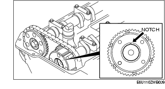
10. Verify that the groove of the rotor and notch of the cover on the variable valve timing actuator are aligned and fitted.
11. Install the cylinder head cover. (See Cylinder Head Cover Installation Note.)
12. Install the ventilation hose.
13. Connect the P/S oil pump connector.
14. Connect the CMP sensor connector.
15. Connect the OCV connector.
16. Install the spark plugs. (See SPARK PLUG REMOVAL/INSTALLATION [L8, LF, L3, L3 Turbo].)
17. Install the ignition coils. (See IGNITION COIL REMOVAL/INSTALLATION [L8, LF, L3, L3 Turbo].)
18. Install the charge air cooler.
19. Connect the negative battery cable.