 |
am6zzw00007183
TIMING CHAIN REMOVAL/INSTALLATION [L3 Turbo]
id0110b3801000
1. Disconnect the negative battery cable.
2. Remove the under cover.
3. Remove the front tire (RH).
4. Remove the splash shield (RH).
5. Remove the charge air cooler. (SeeINTAKE-AIR SYSTEM REMOVAL/INSTALLATION [L3 Turbo].)
6. Remove the high pressure fuel pump. (See HIGH PRESSURE FUEL PUMP REMOVAL/INSTALLATION [L3 Turbo].)
7. Remove the ignition coils. (See IGNITION COIL REMOVAL/INSTALLATION [L8, LF, L3, L3 Turbo].)
8. Disconnect the OCV connector.
9. Disconnect the CMP sensor connector.
10. Disconnect the P/S oil pump connector.
11. Remove the ventilation hose.
12. Remove the cylinder head cover. (See Cylinder Head Cover Removal Note.)
13. Loosen the water pump pulley installation bolt and remove the drive belt. (See DRIVE BELT REPLACEMENT [L3 Turbo].)
14. Remove the CKP sensor. (See CRANKSHAFT POSITION (CKP) SENSOR REMOVAL/INSTALLATION [L3 Turbo].)
15. Remove the P/S oil pump with the hoses and pipes still connected. (See POWER STEERING OIL PUMP REMOVAL/INSTALLATION [L8, LF, L3, L3 Turbo].)
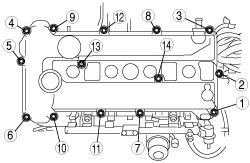
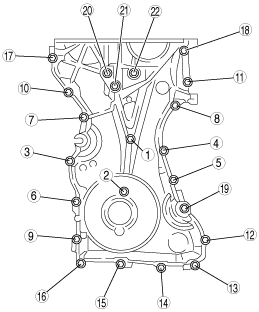
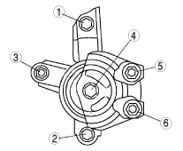
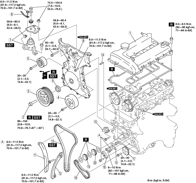
16. Remove in the order indicated in the figure.
17. Install in the reverse order of removal.
18. Start the engine and inspect and adjust the following:
19. Perform a road test and verify that there is no abnormal vibration or noise.
am6zzw00007183
|
|
1
|
Cylinder head cover
|
|
2
|
Crankshaft pulley lock bolt
|
|
3
|
Crankshaft pulley
|
|
4
|
Water pump pulley
|
|
5
|
Front drive belt idler pulley
|
|
6
|
Engine ground
|
|
7
|
No. 3 engine mount rubber, No. 3 Engine joint bracket
|
|
8
|
Engine front cover
|
|
9
|
Front oil seal
|
|
10
|
Chain tensioner
(See Chain Tensioner Removal Note.)
|
|
11
|
Tensioner arm
|
|
12
|
Chain guide
|
|
13
|
Timing chain
|
|
14
|
Oil jet
|
|
15
|
Oil pump chain tensioner
|
|
16
|
Oil pump chain guide
|
|
17
|
Oil pump driven sprocket
|
|
18
|
Oil pump chain
|
|
19
|
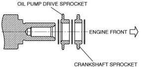
Crankshaft sprocket
|
|
20
|
Oil pump drive sprocket
|
Cylinder Head Cover Removal Note
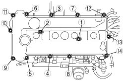
1. Loosen the cylinder head cover bolts in the order shown in the figure.
am6zzw00007184
|
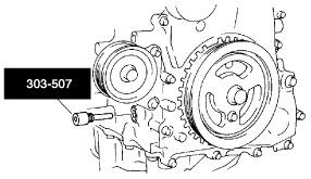
Crankshaft Pulley Lock Bolt Removal Note
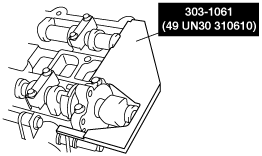
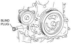
1. Remove the cylinder block lower blind plug and install the SST.
am6zzw00007185
|
2. Rotate the crankshaft clockwise so that the No.1 cylinder is at TDC of the compression stroke. (Position crank weight contacts SST.)
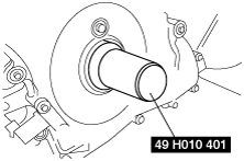
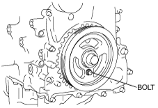
3. Install the SST to the crankshaft pulley and lock the crankshaft against rotation.
am6zzw00007186
|
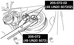
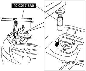
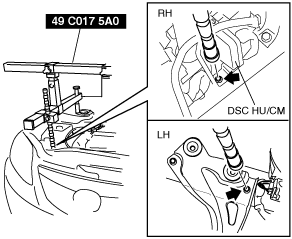
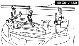
No.3 Engine Mount Rubber, No.3 Engine Joint Bracket Removal Note
1. Remove the air cleaner. (See INTAKE-AIR SYSTEM REMOVAL/INSTALLATION [L3 Turbo].)
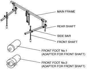
2. Install the SST using the following procedure.
am6zzw00007187
|
am6zzw00007188
|
am6zzw00007189
|
3. Support the engine using the SST.
am6zzw00007190
|
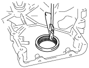
Engine Front Cover Removal Note
1. Remove the front oil seal using a flathead screwdriver or similar tool.
am6zzw00007191
|
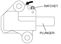
Chain Tensioner Removal Note
1. Press the timing chain tensioner ratchet to the left using a thin flathead screwdriver (precision screwdriver) to unlock the plunger.
am6zzw00007192
|
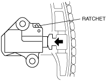
2. Slowly press the plunger back in the direction shown in the figure while pressing the ratchet.
am6zzw00007193
|
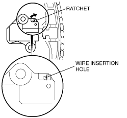
3. Release the ratchet with the plunger still pressed down.
am6zzw00007194
|
4. Press-in the plunger until the ratchet position is as indicated in the figure, and then insert the wire to lock the plunger.
am6zzw00007195
|
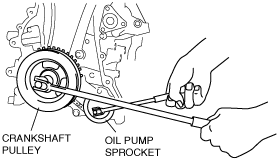
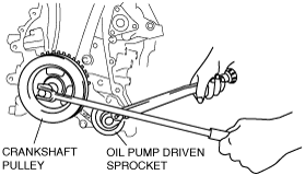
Oil Pump Driven Sprocket Removal Note
1. Temporarily install the crankshaft pulley and crankshaft pulley lock bolt to the crankshaft, and lock the oil pump against rotation as shown in figure.
am3zzw00004319
|
2. Remove the oil pump driven sprocket, and then remove the crankshaft pulley and crankshaft pulley lock bolt.
Oil Pump Drive Sprocket Installation Note
1. The oil pump drive sprocket has the assembly direction as shown in the figure.
am6zzw00007196
|
Oil Pump Driven Sprocket Installation Note
1. Temporarily install the crankshaft pulley and crankshaft pulley lock bolt to the crankshaft, and lock the oil pump against rotation as shown in figure.
am3uuw00001568
|
2. Install the oil pump driven sprocket, and then remove the crankshaft pulley and crankshaft pulley lock bolt.
Timing Chain Installation Note
1. Install the SST to the camshaft as shown in the figure.
am6zzw00007197
|
2. Install the timing chain.
3. Remove the wire or paper clip from the chain tensioner piston and apply tension to the timing chain.
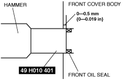
Front Oil Seal Installation Note
1. Apply clean engine oil to a new front oil seal.
2. Push the front oil seal in the engine front cover by hand.
3. Use the SST to tap in the front oil seal.
am6zzw00007198
|
am6zzw00007199
|
Engine Front Cover Installation Note
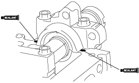
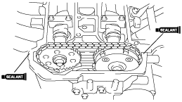
1. Apply silicone sealant to the engine front cover.
am6zzw00007200
|
2. Tighten the engine front cover installation bolts in the order shown in the figure.
am6zzw00007201
|
|
Installation Position
|
Tightening Torque N·m {kgf·m, ft·lbf}
|
|
1—18
|
8.0—11.5 N·m {81.6—117.2 kgf·cm, 70.9—101.7 in·lbf}
|
|
19—22
|
40—55 {4.1—5.6, 29.7—40.5}
|
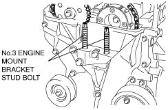
No.3 Engine Mount Rubber, No.3 Engine Joint Bracket Installation Note
1. Tighten the No.3 engine mount bracket stud bolts.
am6zzw00007202
|
2. Temporarily tighten the No.3 engine mount rubber installation bolts.
3. Install the No.3 engine joint bracket and tighten the bolts and nuts in the order shown in the figure.
am6zzw00007203
|
Crankshaft Pulley Lock Bolt Installation Note
1. Install the SST to the camshaft as shown in the figure.
am6zzw00007197
|
2. Verify that cylinder No.1 is at TDC of the compression stroke. (Position crank weight contacts SST.)
3. To position the crankshaft pulley, temporarily tighten it and, using a suitable bolt (M6 X 1.0 length 25—35 mm {0.99—1.37 in}), fix the crankshaft pulley to the engine front cover.
am6zzw00007204
|
4. Install the SSTs to the crankshaft pulley, lock the crankshaft against rotation, and tighten the crankshaft pulley lock bolt using the following two steps.
am6zzw00007186
|
5. Remove the bolt (M6 X 1.0 length 25—35 mm {0.99—1.37 in}) installed to the crankshaft pulley.
6. Remove the SST from the camshaft.
7. Remove the SST installed in the cylinder block lower blind plug hole.
8. Rotate the crankshaft clockwise two turns and inspect the valve timing.
9. Install the cylinder block lower blind plug.
am6zzw00007205
|
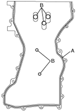
Cylinder Head Cover Installation Note
1. Apply silicone sealant to the areas shown in the figure.
am6zzw00007206
|
am6zzw00007207
|
2. Tighten the cylinder head cover bolts in the order shown in the figure.
am6zzw00007208
|